Before getting started, I’d like to thank my friend and neighbor, Lewis, for generously sharing so many fun and fascinating devices with me. Here’s to him! 🍻
I’ve studied telecommunications for 6 years. During both my undergraduate and master’s studies, I completed numerous experiments related to DVB (Digital Video Broadcasting). I was in a course named “ELEC5510 Satellite Communication Systems” where most of the labs involved SDRs and were carried out using MATLAB Simulink or GNU Radio to build flow graphs for implementing DVB protocols like DVB-T/H, DVB-T2 and DVB-S/S2.
Even though I had become quite familiar with entire process, I had never actually worked with a real DVB-T signal. All the signals I dealt with during those experiments were simulated and not necessarily compliant with the DVB-T standard. That changed when Lewis gave me a DYNALINK TV tuner, which inspired me to start experimenting with generating real DVB-T signals.
Initially, my plan was to use GNURadio to generate a standard DVB-T signal and then feed it into the TV tuner. However, I didn’t have access to a USRP or any other device capable of transmitting with a sample rate above 8 Msps, so I wasn’t able to generate such RF signals at that time.
Fortunately, when I talked to Lewis about this, he mentioned that he happened to have a DVB-T encoder and was more than happy to lend it to me—a stroke of luck for which I’m truly grateful. Lewis lives just across the street, so it took me less than five minutes to meet him and pick it up. Even better, he kindly agreed to let me take it apart and explore its internals, which I deeply appreciate as a gesture of trust.
Overview
The KT-FX1 from ZYCAST is a professional DVB-T encoder and modulator designed for broadcasting applications by a Taiwan Company. It supports real-time encoding of input video signals from HDMI and directly outputs DVB-T compliant RF signals, suitable for testing, signal generation, and small-scale transmission setups.
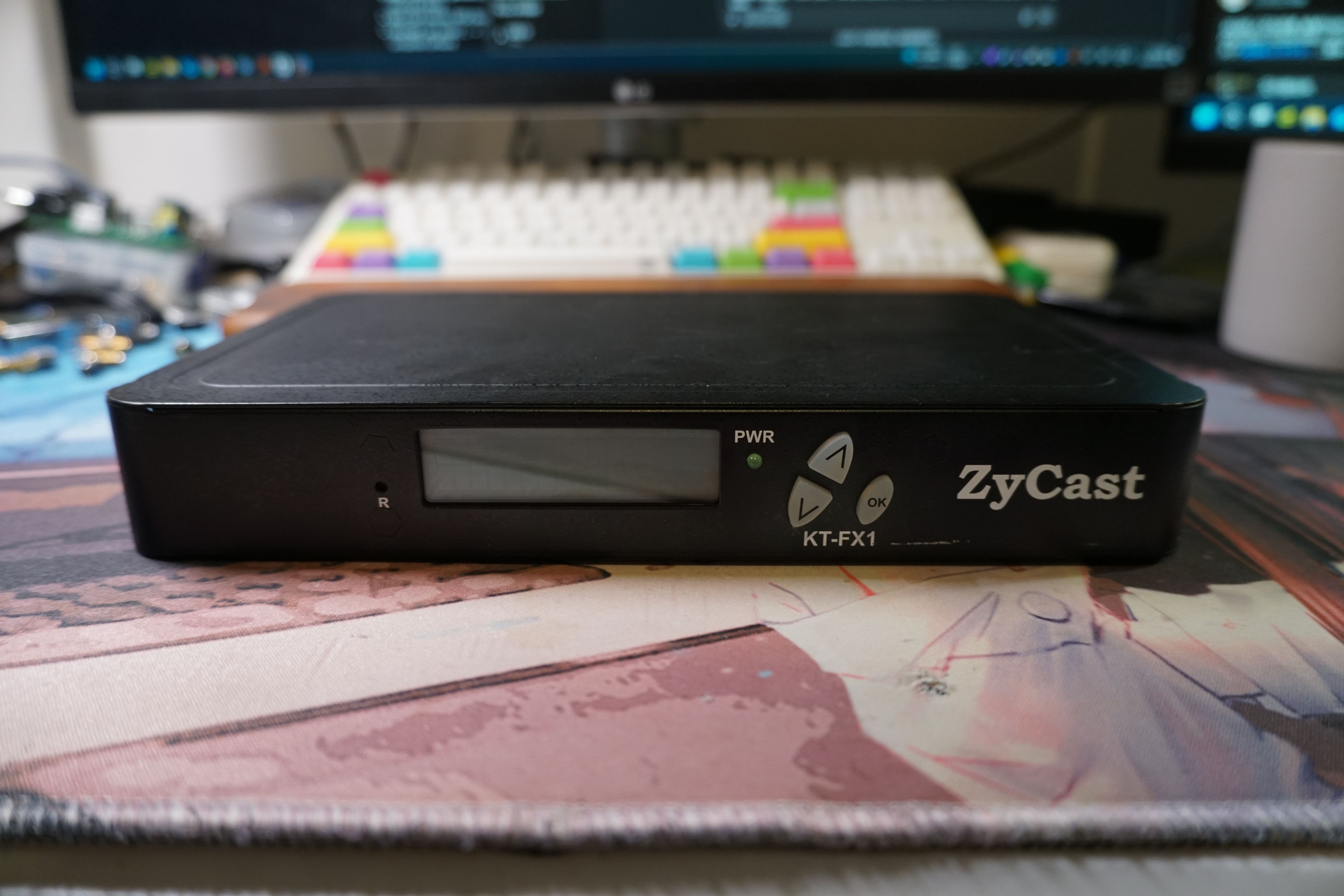
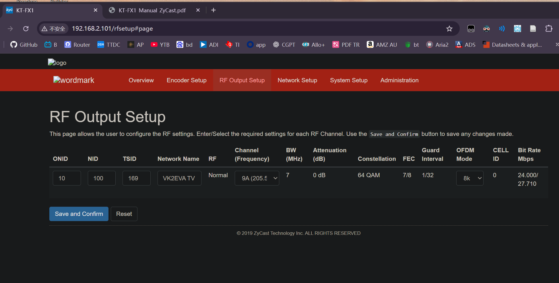
It supports a limited set of fixed parameters: the code rate is restricted to 7/8, the guard interval to 1/32, and the modulation scheme to 64-QAM. The OFDM mode can be configured for either 2K or 8K operation. Despite these constraints, its performance is nice, MER 39 dB
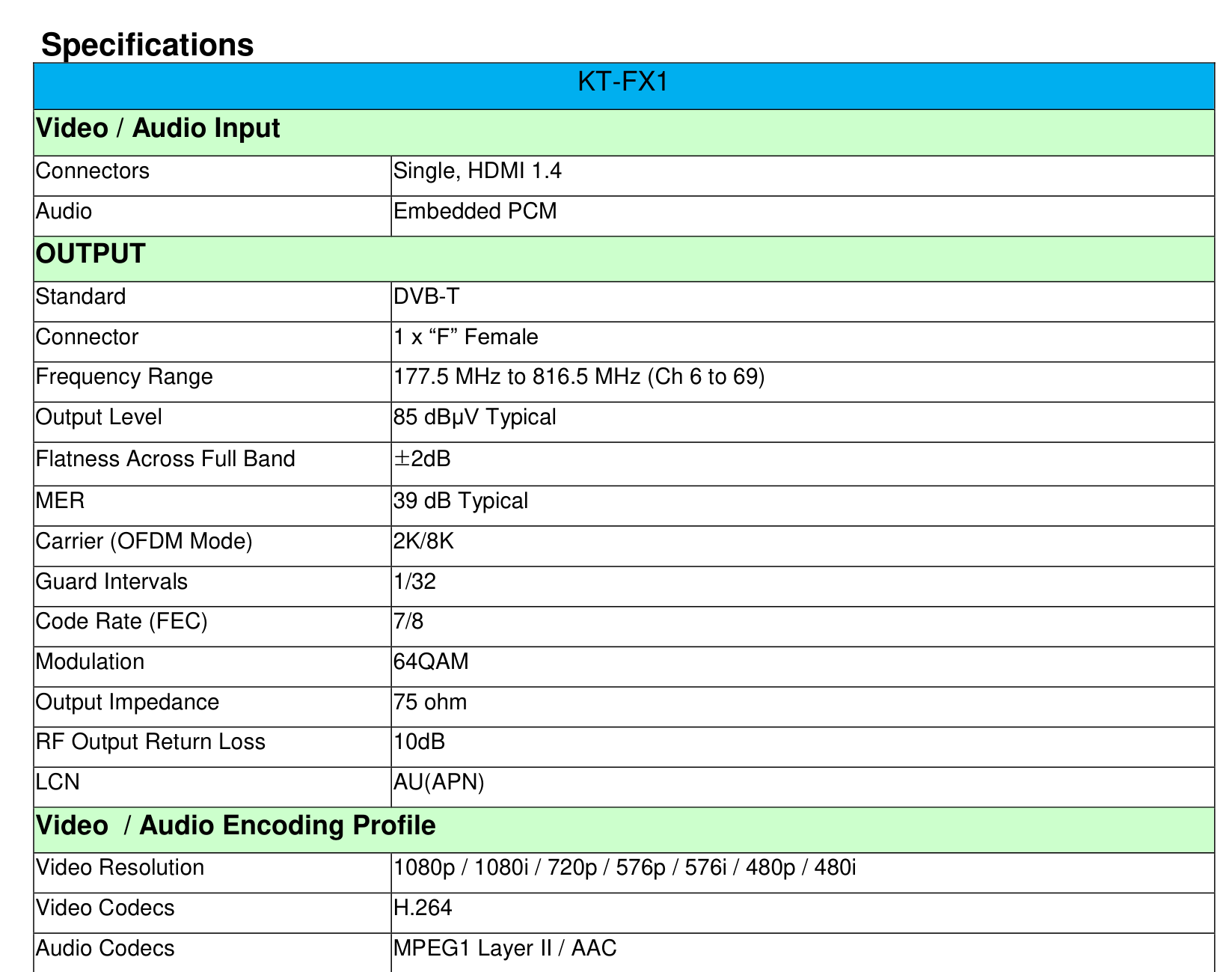
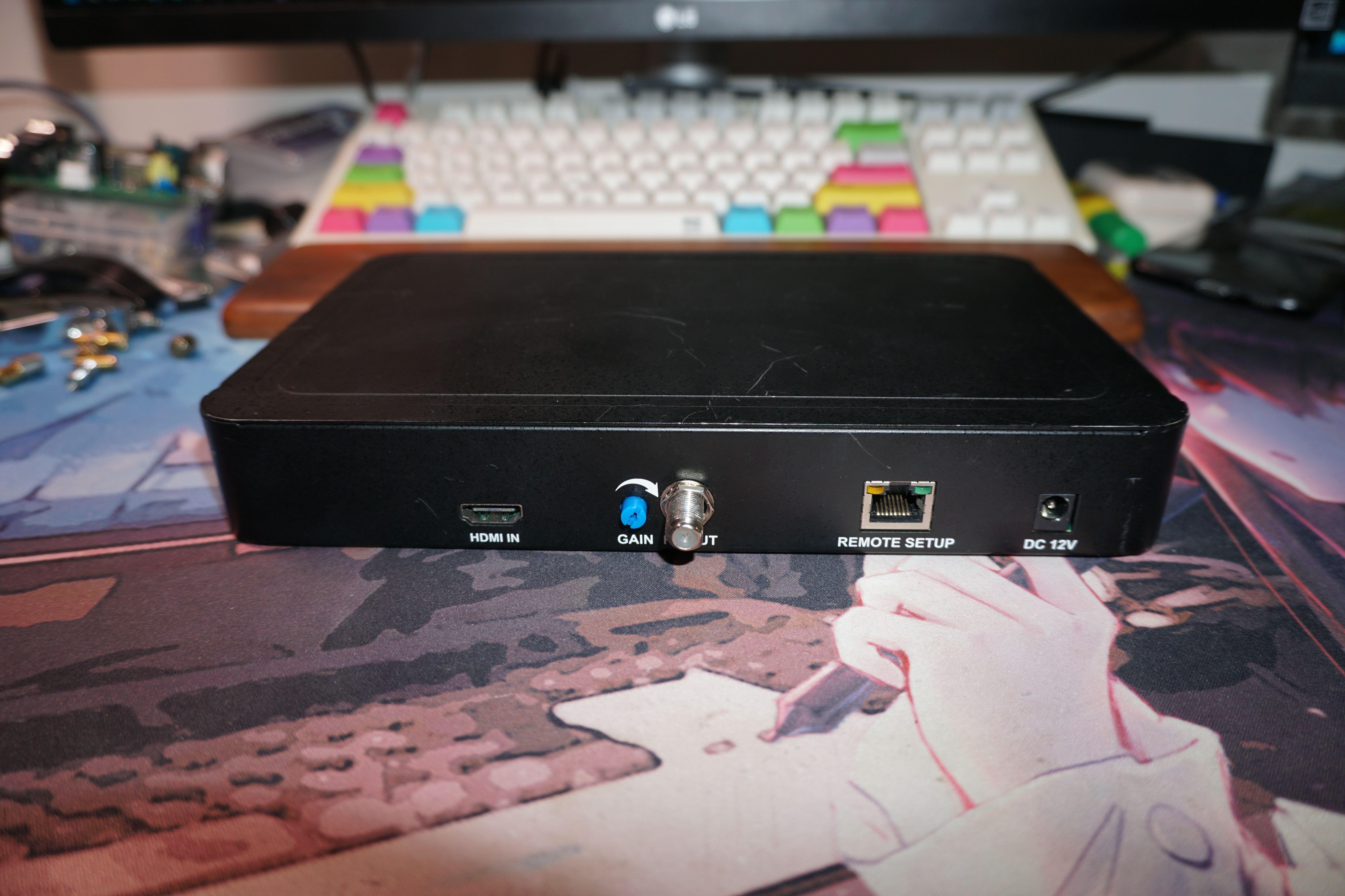
On the back side, it has an HDMI input for video signals, along with an adjustable attenuator to reduce the output power and prevent overdriving the target device. The RF output uses a standard TV connector with 75-ohm impedance. There is also an Ethernet port for convenient device control, and a 12 V power input.
Analysis
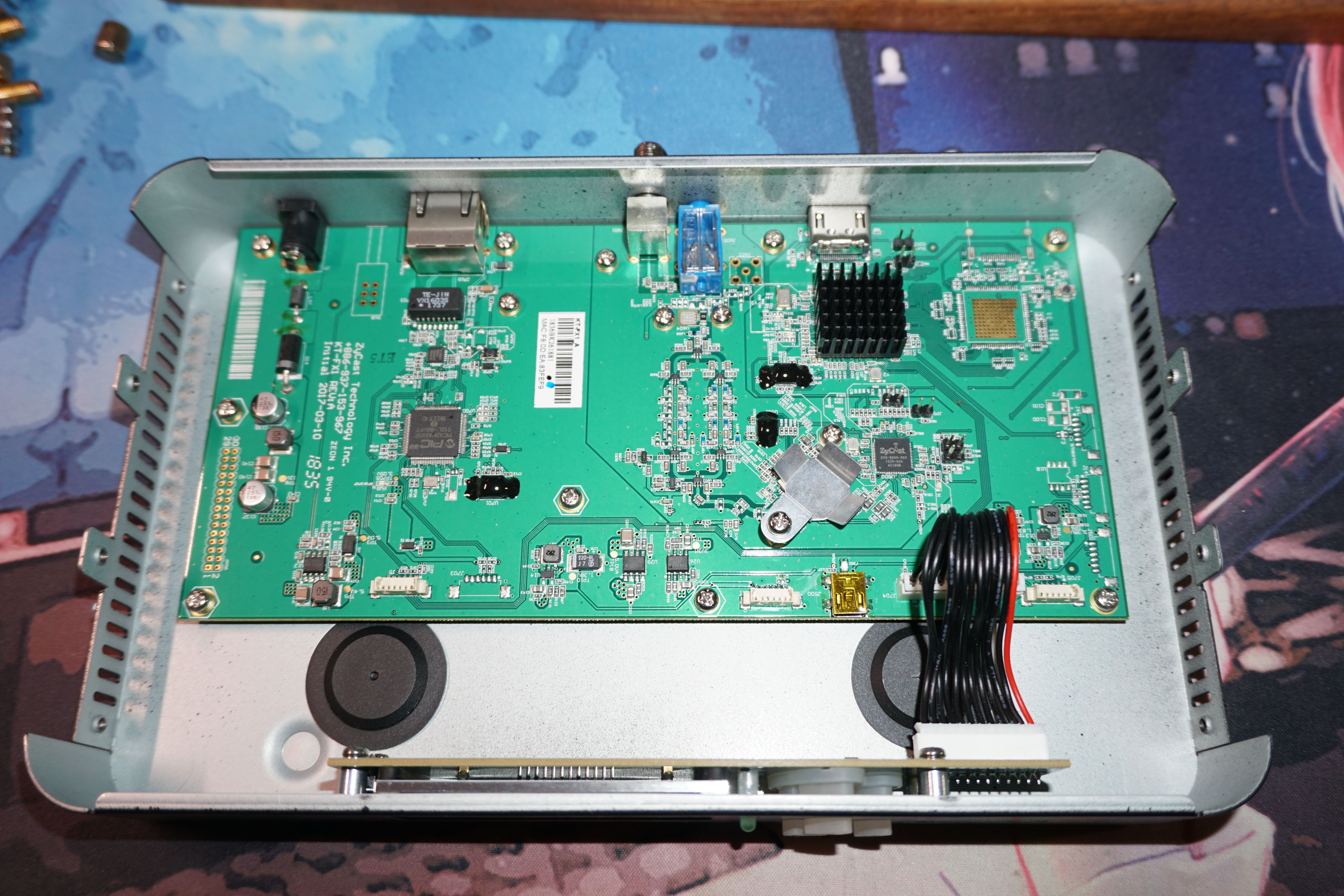
After opening the device, it becomes clear that it is divided into two boards: the mainboard on top and a smaller board with the display and buttons below. On the left side of the mainboard are the power input, ferrite beads, filtering components, and reverse-polarity protection. There is also an unpopulated switch footprint, apparently intended to control the enable pin of the DC-DC converter in the lower left corner, though it was never soldered. Below the Ethernet port are the network transformer and Ethernet PHY, along with a PIC microcontroller, which likely serves as the main controller for the web interface and encoder chip.
Moving on to the RF section: the signal path starts from the HDMI input, feeding into an integrated encoder, which is connected to a small chip beneath it—most likely a multi-channel DAC. From there, the signal passes into an ADRF vector modulator, followed by a filter array, and finally through an adjustable attenuator before reaching the RF output.
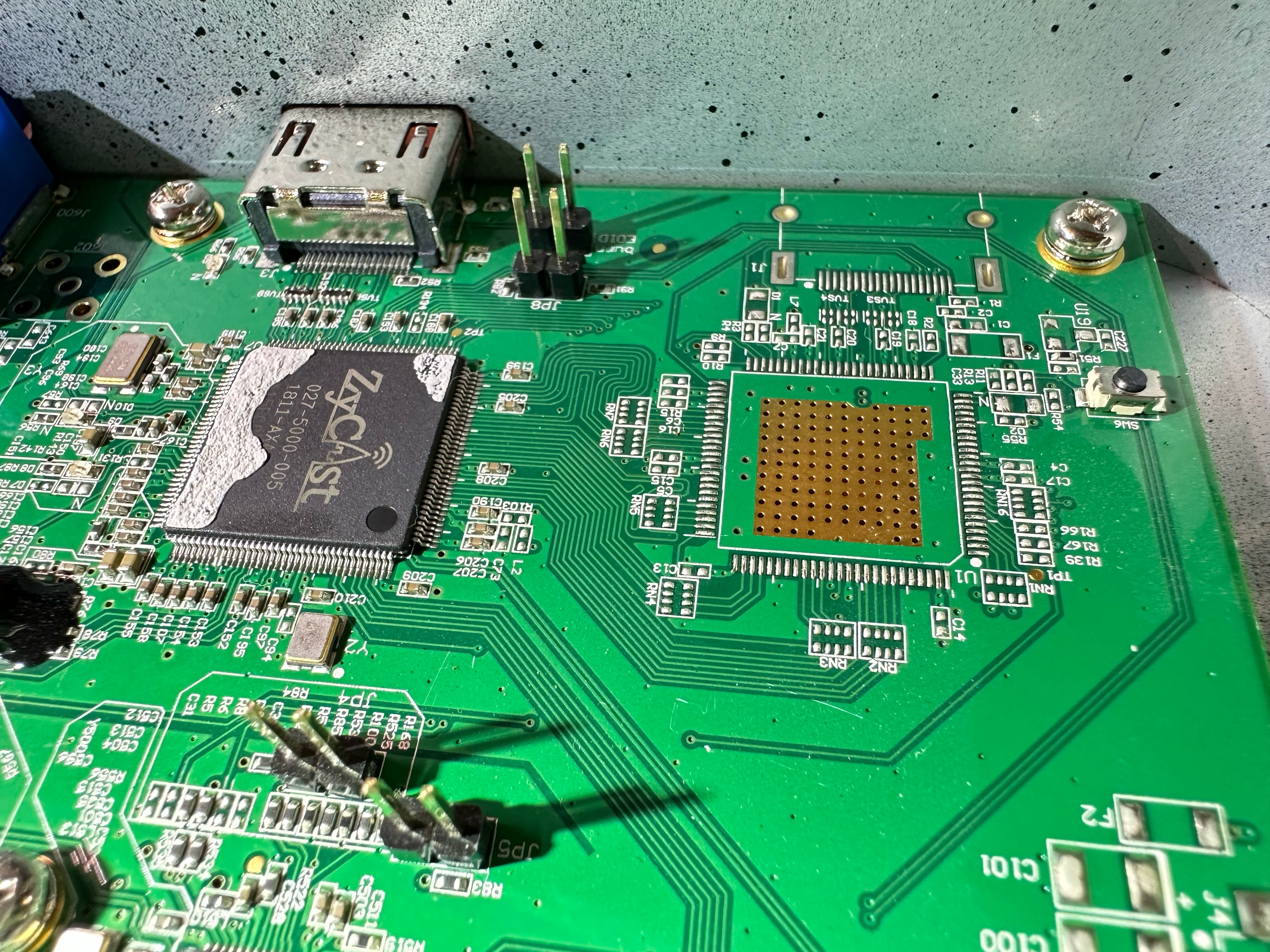
After removing the heatsink from the encoder chip, the IC marking 027-5000-005 becomes visible. This is very likely an ASIC. While the DVB-T processing chain is well-suited for FPGA implementation, once production volumes increase, migrating to an ASIC design becomes far more efficient.
To the right, there is an unpopulated HDMI connector footprint along with an empty chip position. This was likely intended either for signal loop-through or as a second input. It suggests that higher-end models in the same product line may share a common PCB design to reduce manufacturing costs.
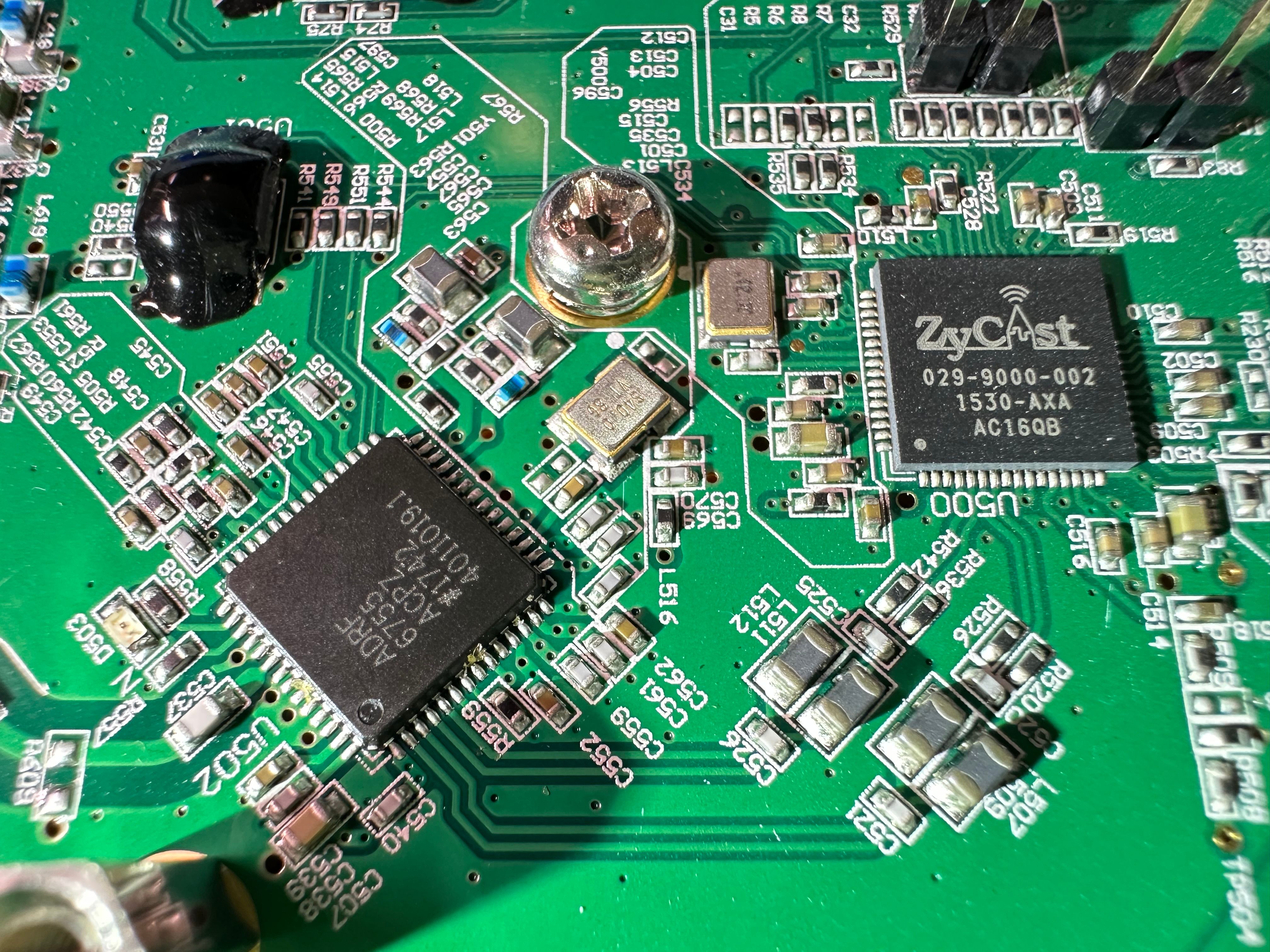
The baseband section is handled by another ASIC, marked 029-9000-002. Its function is to convert digital signals into 7 MHz bandwidth differential IQ baseband signals, essentially performing the role of a dual-channel high-speed DAC. The IQ outputs exit directly below the chip and pass through resistors and common-mode Nyquist filters to remove out-of-band harmonics. The filtered signals are then fed into the ADRF6755 integrated vector modulator.
The ADRF6755 is an integrated IQ vector modulator from Analog Devices, designed for high-performance RF signal generation. It accepts differential IQ baseband inputs and converts them into a modulated RF output with high linearity and low distortion. The device supports a wide frequency range and is suitable for applications such as DVB-T/DVB-T2 transmission, signal simulation, and wireless communication systems. Its integrated architecture simplifies RF chain design by combining multiple functions into a single compact component.
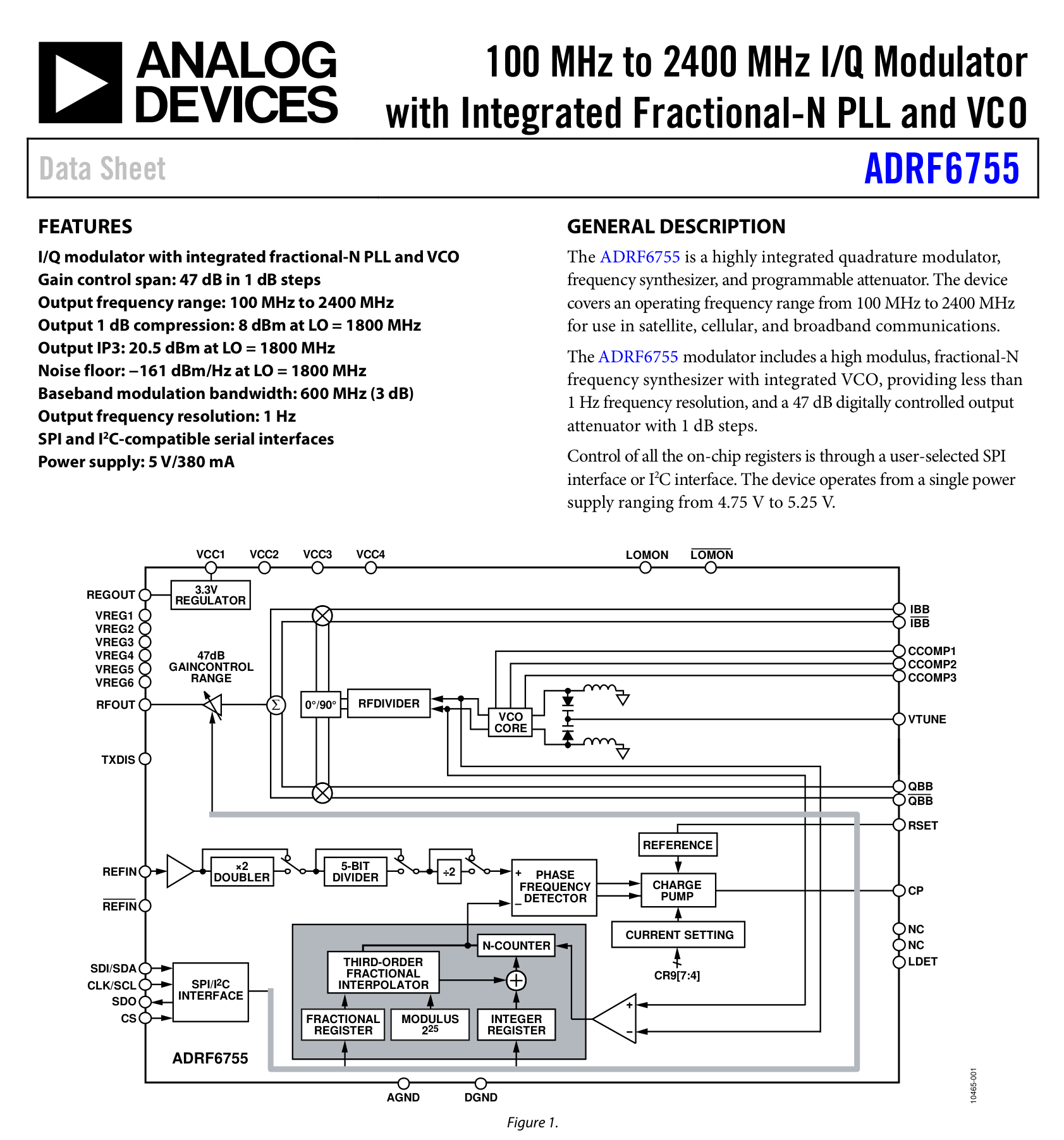
It’s worth noting that this chip can operate up to around 2.4 GHz, meaning it is fully capable of higher-frequency operation. However, the software imposes restrictions, which is quite reasonable given the need to comply with radio regulations.
A 40 MHz active crystal oscillator is used here. It is important to ensure good performance on these oscillators for both the IQ baseband and the RF carrier, as this directly affects the performance of high-order QAM modulation; phase noise can significantly distort the constellation diagram.
Underneath those black blobs of adhesive are FLASH Memory, used to store the firmware. It’s unclear why they’re covered in glue—perhaps to prevent the chips from coming loose, or maybe as a deterrent against tampering or reverse engineering.
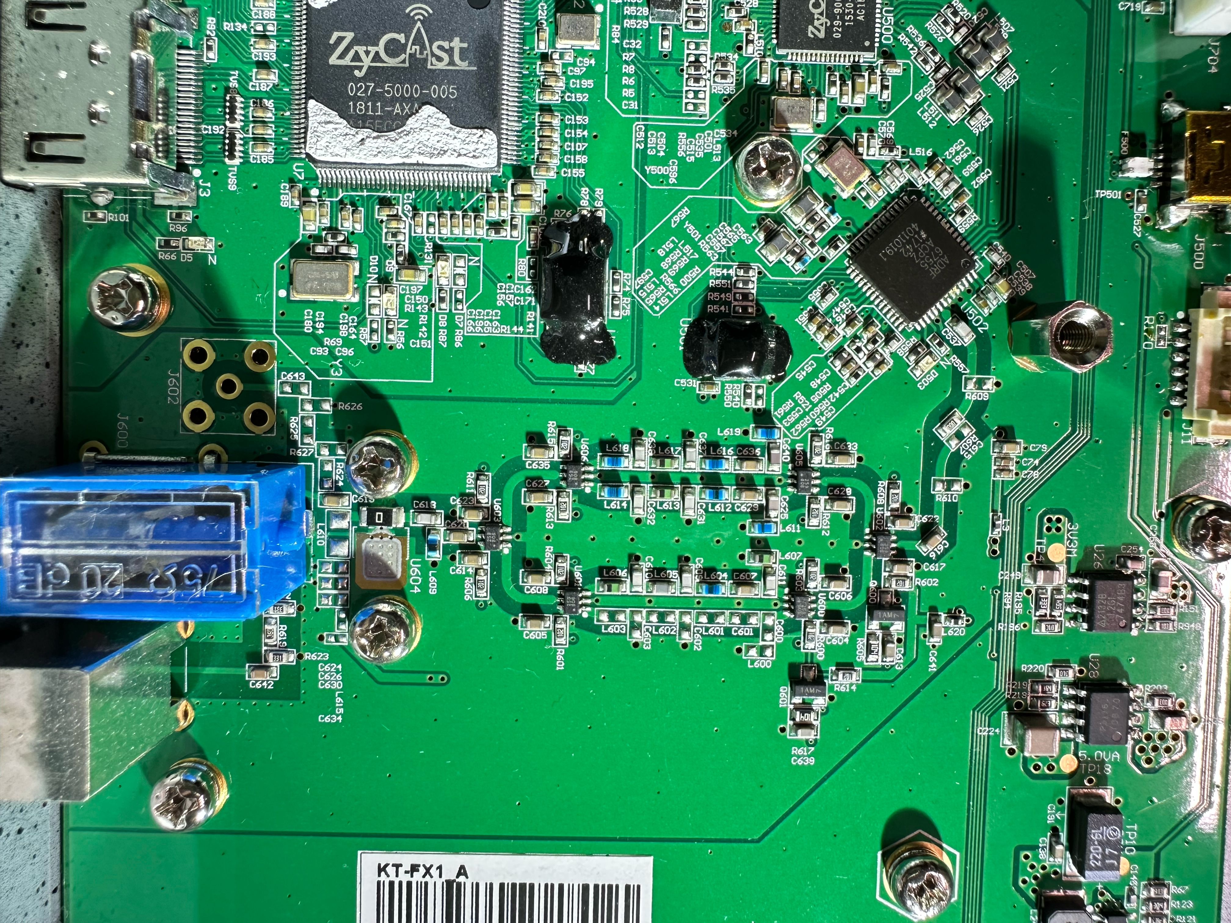
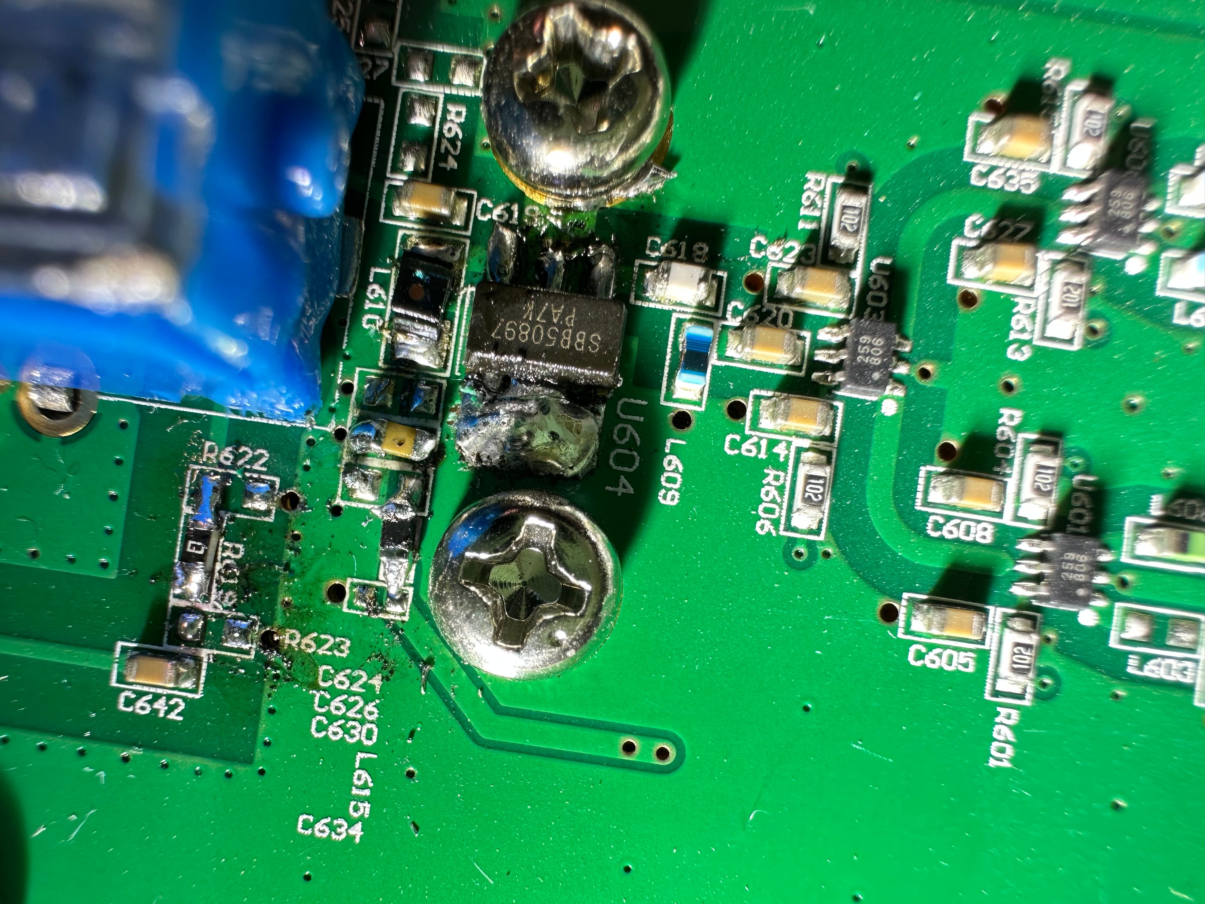
After the RF filters, there is a reserved footprint for an amplifier labeled U604. In practice, the device’s output power is relatively low, peaking at around -60 dBm, which aligns with the absence of this amplifier. Additionally, the ADRF vector modulator contains an internal amplifier, but I did not find any way to adjust its gain; this is likely also restricted by the software.
The large blue plastic attenuator is labeled 75 Ω, 20 dB, indicating an adjustable attenuation range of 20 dB. Through the plastic casing, the internal carbon film is visible; such attenuators are typically composed of three resistors. Before reaching the RF output, the signal also passes through a final resistive attenuator, meaning the signal undergoes significant overall attenuation. If we were to modify this device for HAM TV use, these attenuators would need to be removed—more on that later.
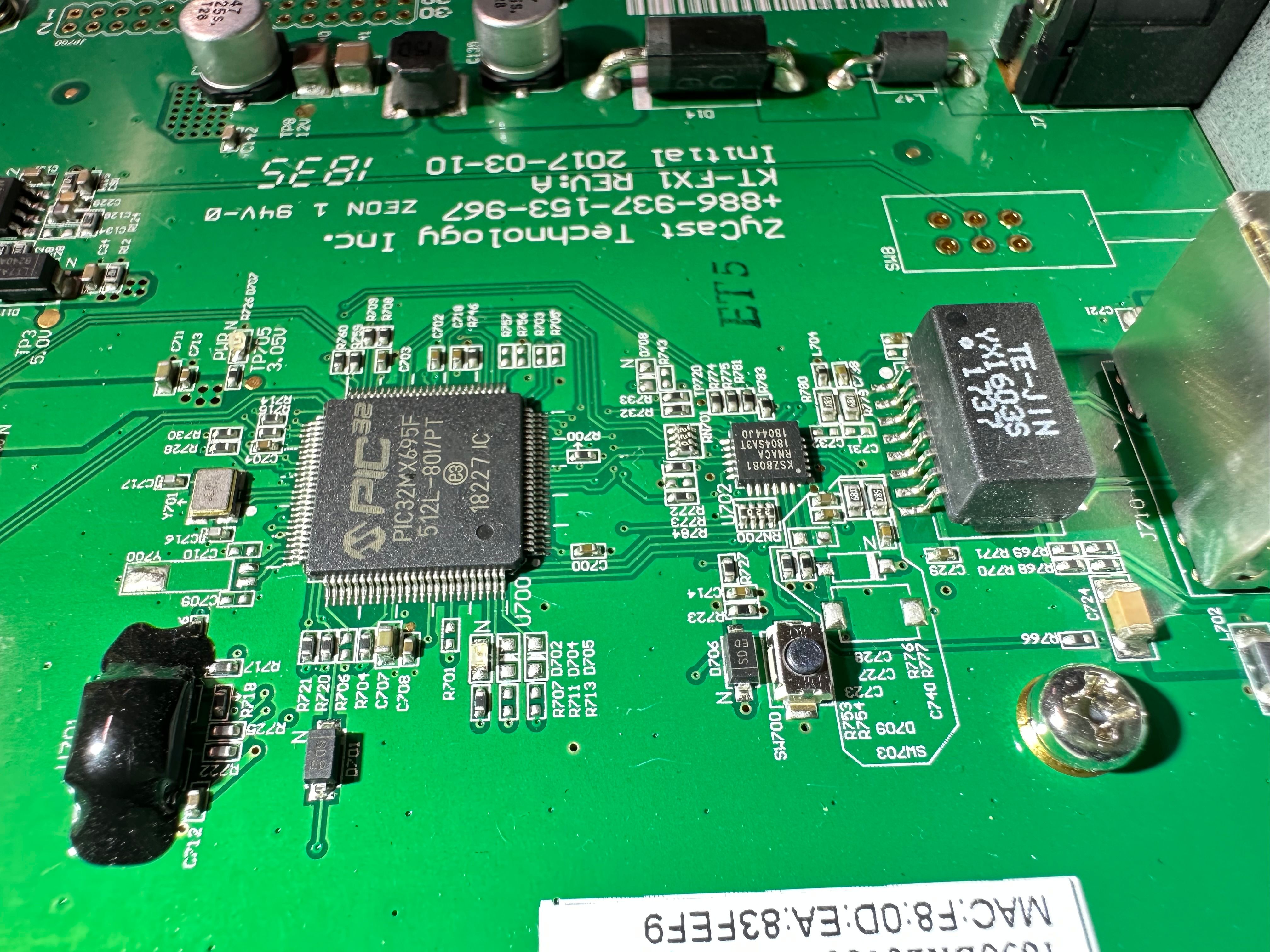
The MCU section is quite simple, so I won’t go into too much detail. Here’s a large photo so you can take a closer look at the components used.
Tests
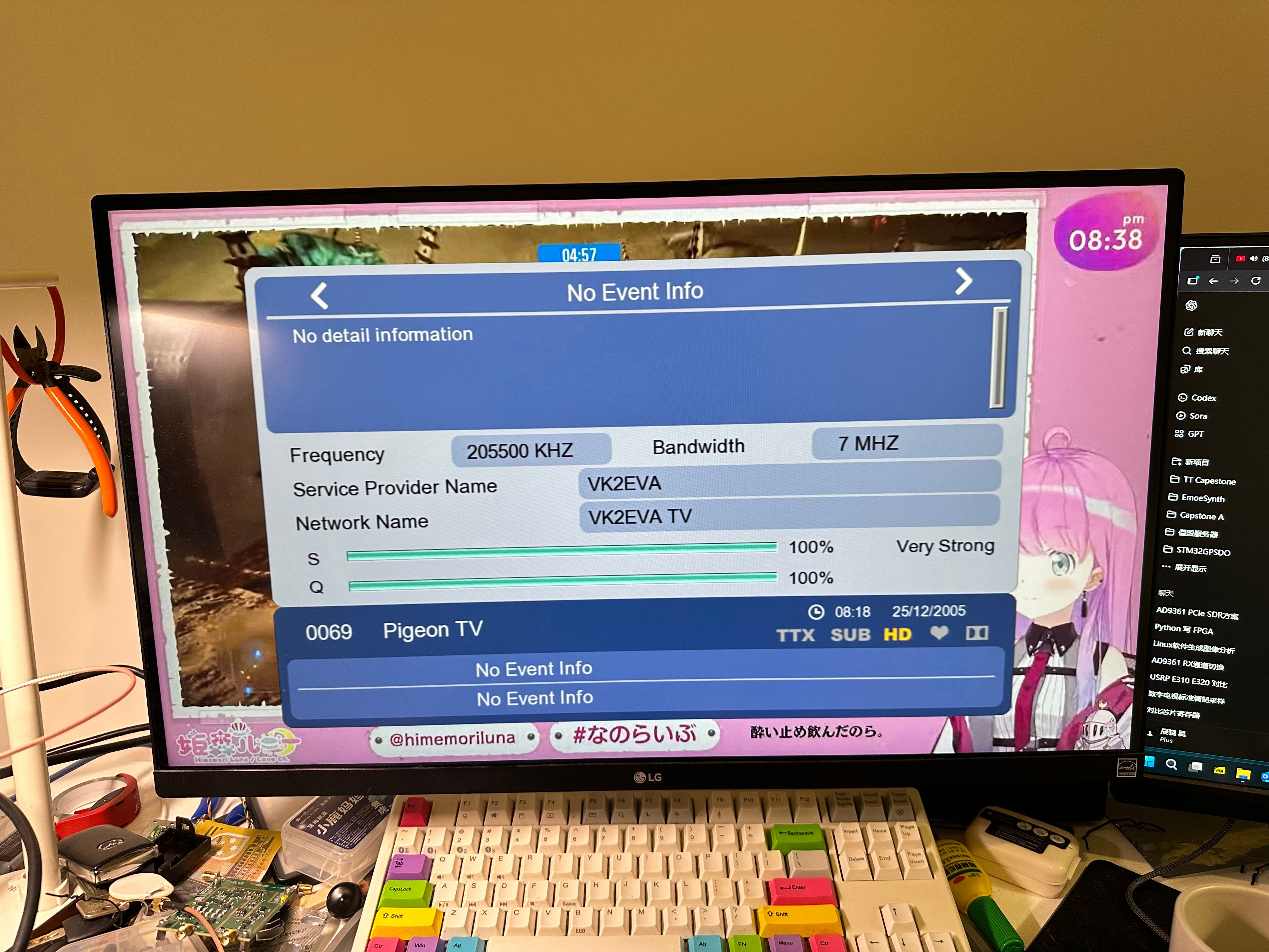
Testing this modulator is very straightforward—simply connect it to the TV tuner. The channels set by our friend Lewis, VK2EVA TV and Pegion TV, are visible, along with their frequency and occupied bandwidth. S indicates signal strength and Q indicates signal quality—both are at 100% levels.
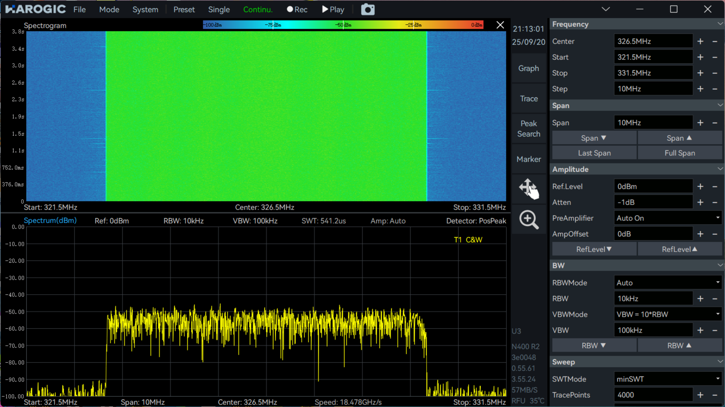
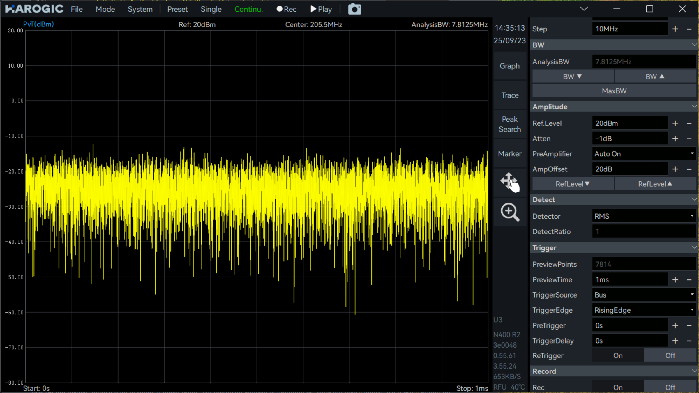
By connecting the device to a HAROGIC SAN-400 real-time spectrum analyzer, we can see the signal strength and occupied bandwidth, which is approximately 6.7 MHz, spectrum showed around -60 dBm.
switch into power detect mode, measuring the total RMS power around -20dBm
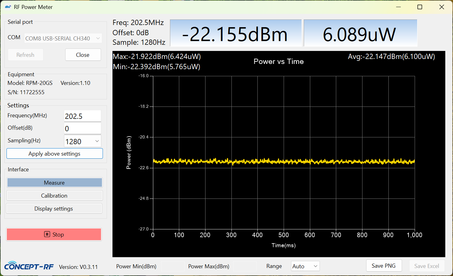
Measuring with a RF power probe by Concept-RF
Modify
Remove the output attenuator and install the empty amplifier
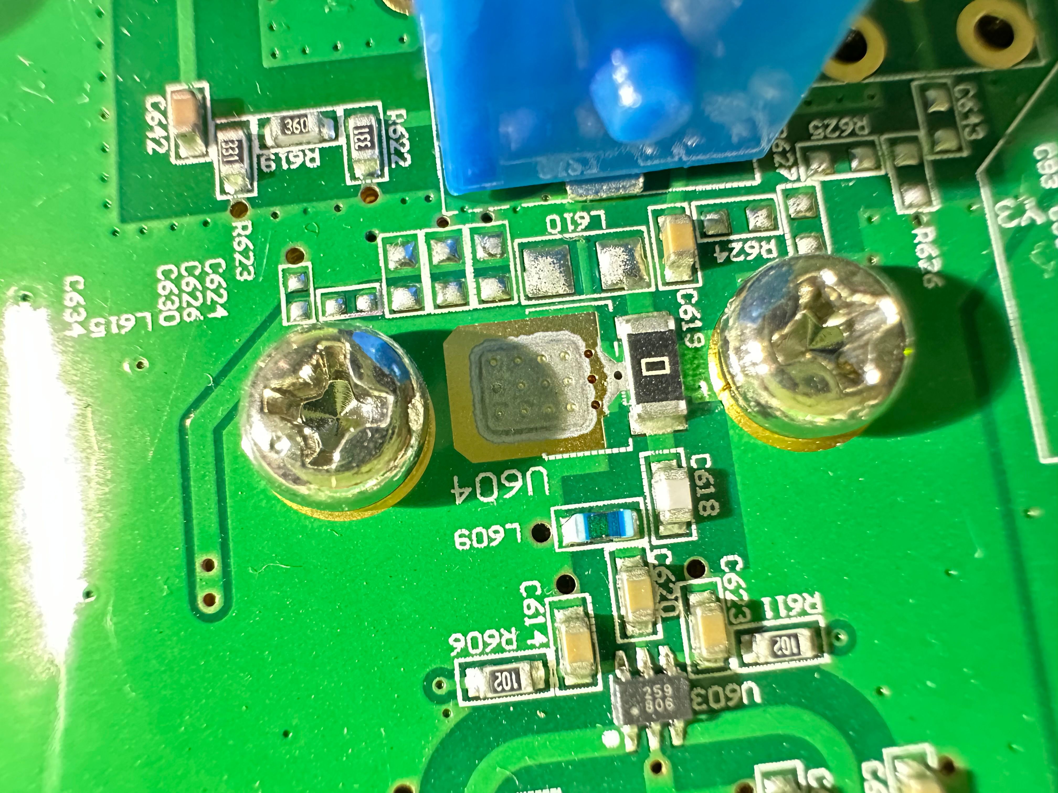
I knew it soldered very bad, it’s just because I don’t want to remove the board out of the case, there’s heatsink on the back.
Conclusion
This DVB-T modulator is a neat, all-in-one way to generate stable RF signals with precise digital modulation. Even though it was designed for regular TV broadcasting, it’s still really interesting for HAM TV enthusiasts. Once you understand how the signal flows through the device, there’s a lot of room to experiment, like removing internal attenuators or using the spare inputs. It’s a great hands-on platform for learning, testing, and getting creative with digital video transmission on amateur radio.