Lewis just handed me a broken Motorola radio tonight. I quickly opened it up in hours, and write this article.
At first glance, the thing looks really high-end — rugged, solid, and packed with that professional vibe. Out of curiosity, I looked it up online, and sure enough, it’s not cheap at all.
I told him I’d give it a try and see if there’s any chance of bringing it back to life. Repairing gear like this is always a bit of a gamble, but it should be fun to take a closer look and figure out what went wrong.
Overview
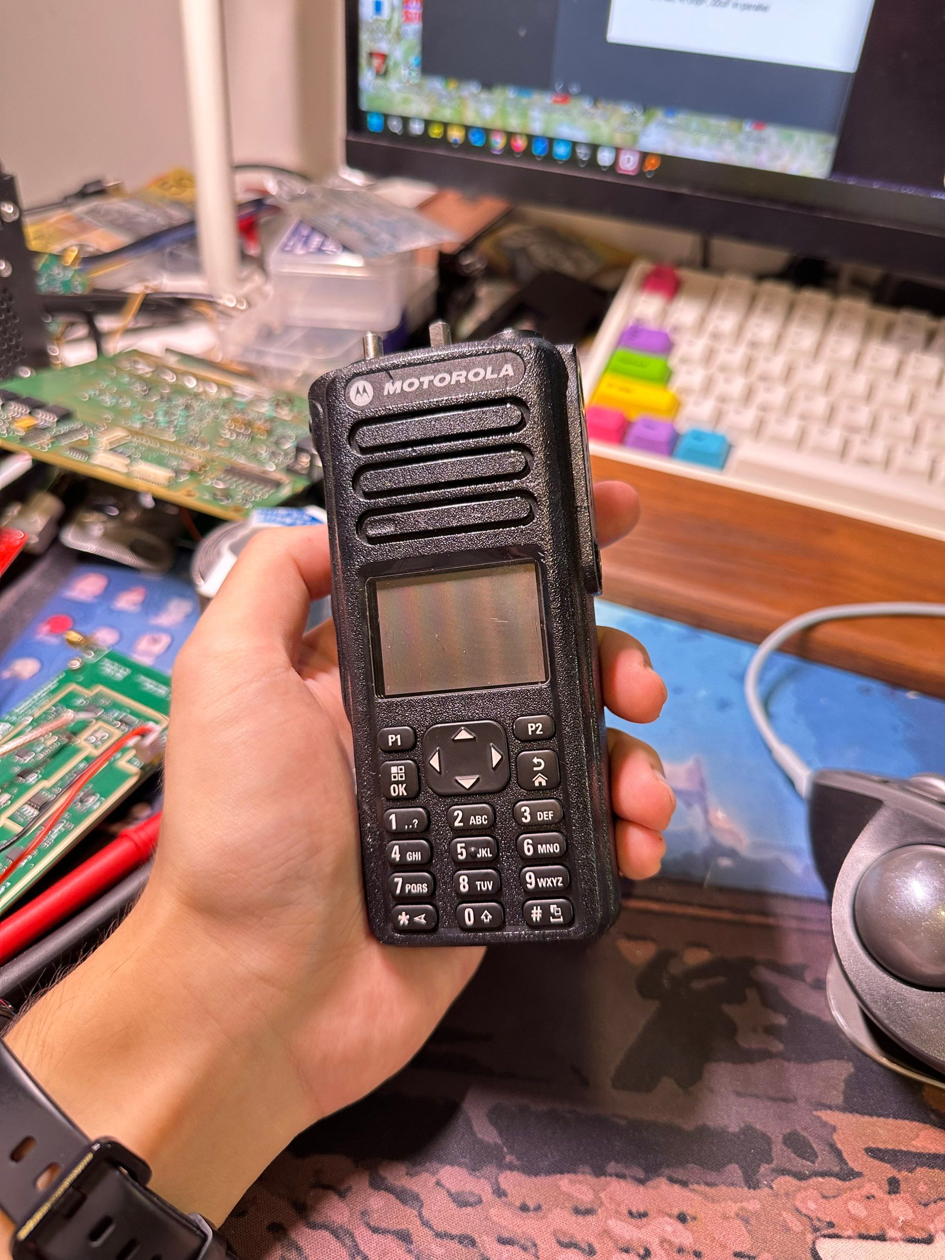
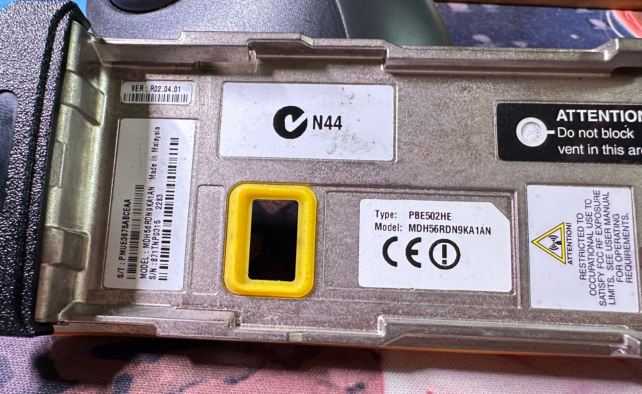
This is a Motorola two-way radio, model MDH56RDN9KA1AN, type PBE502HE. There is no detailed information of this model.
Most likely a Motorola MOTOTRBO series portable digital two-way radio, specifically the DP4801 UHF version.
The MOTOTRBO DP4801 belongs to Motorola’s professional line of digital radios designed for demanding commercial and industrial environments. As a digital portable radio, it combines robust hardware with advanced communication features, offering clearer voice, extended coverage, and improved efficiency compared to traditional analog models.
Teardown
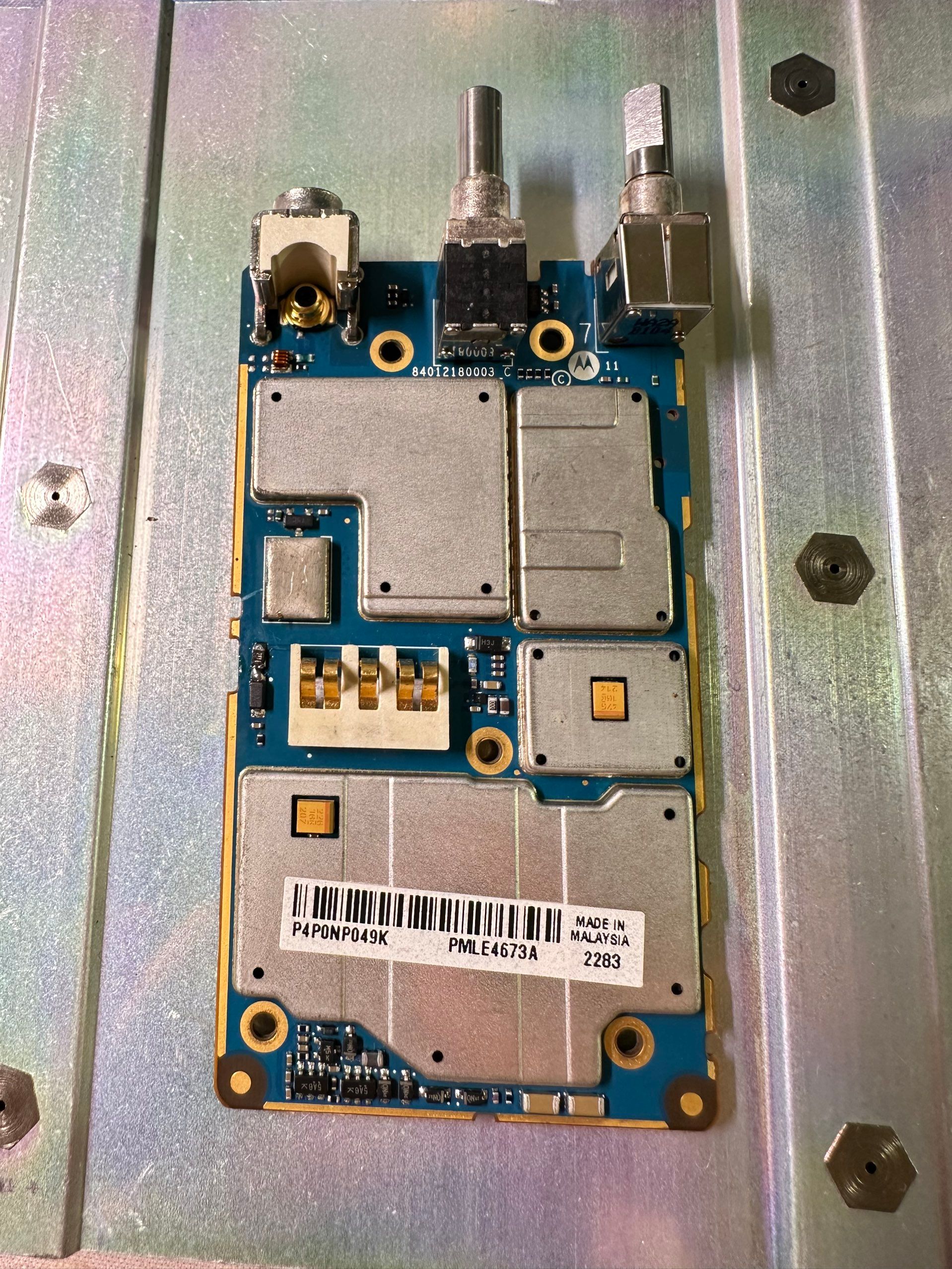
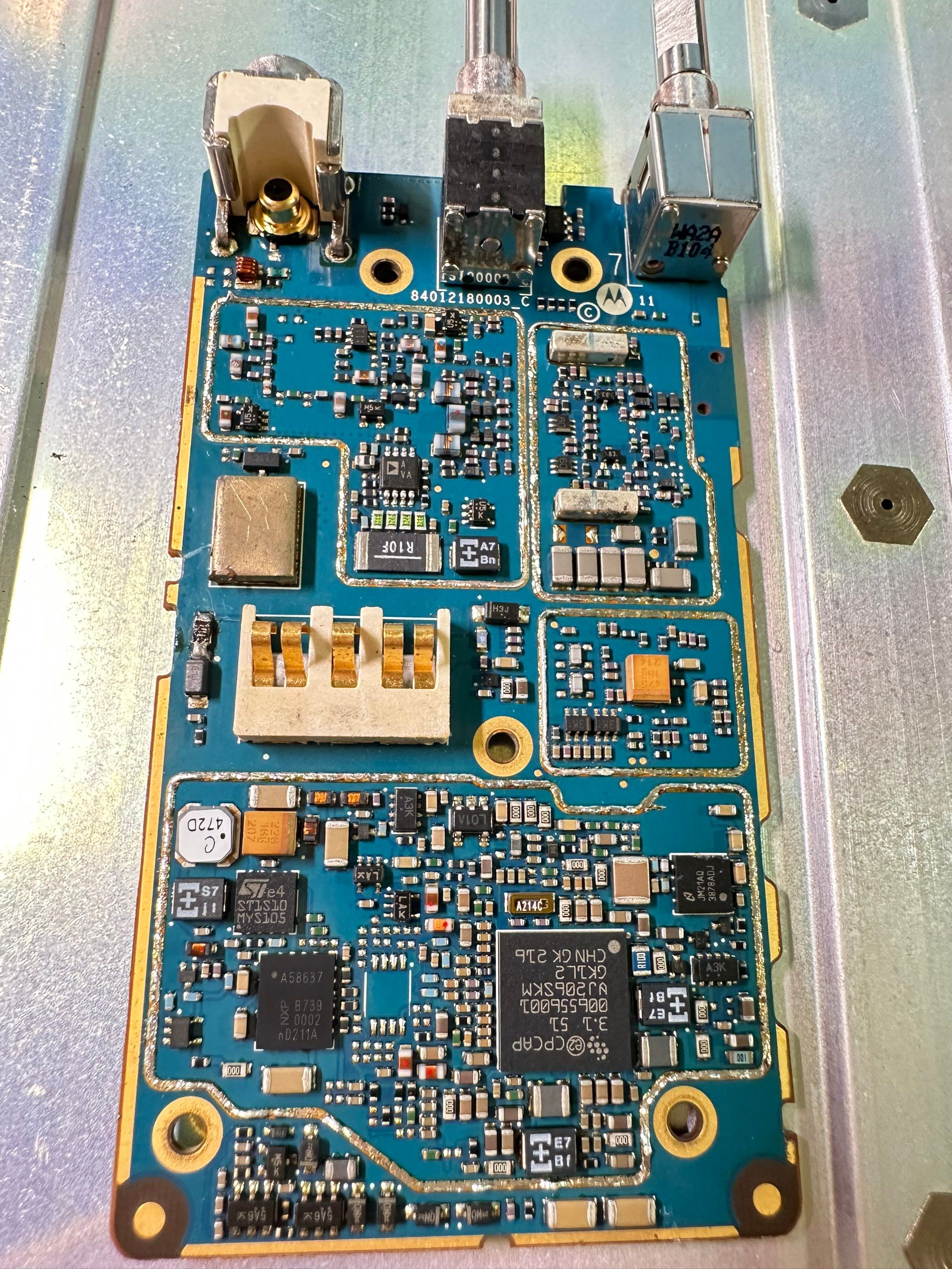
Cracked it open and there’s just one tiny, super dense PCB. This side has the battery connector, plus the antenna port — not coax, just a single metal post where the antenna hooks straight on. Makes sense, but it’s my first time seeing that.
There’s also an external port, looks a bit like MCX, sealed on the back with a rubber plug. No idea what it’s for yet.
Middle’s the channel switch, right side is audio + power, same as most radios. Bottom half is all shield cans — I’ll pop those off next.
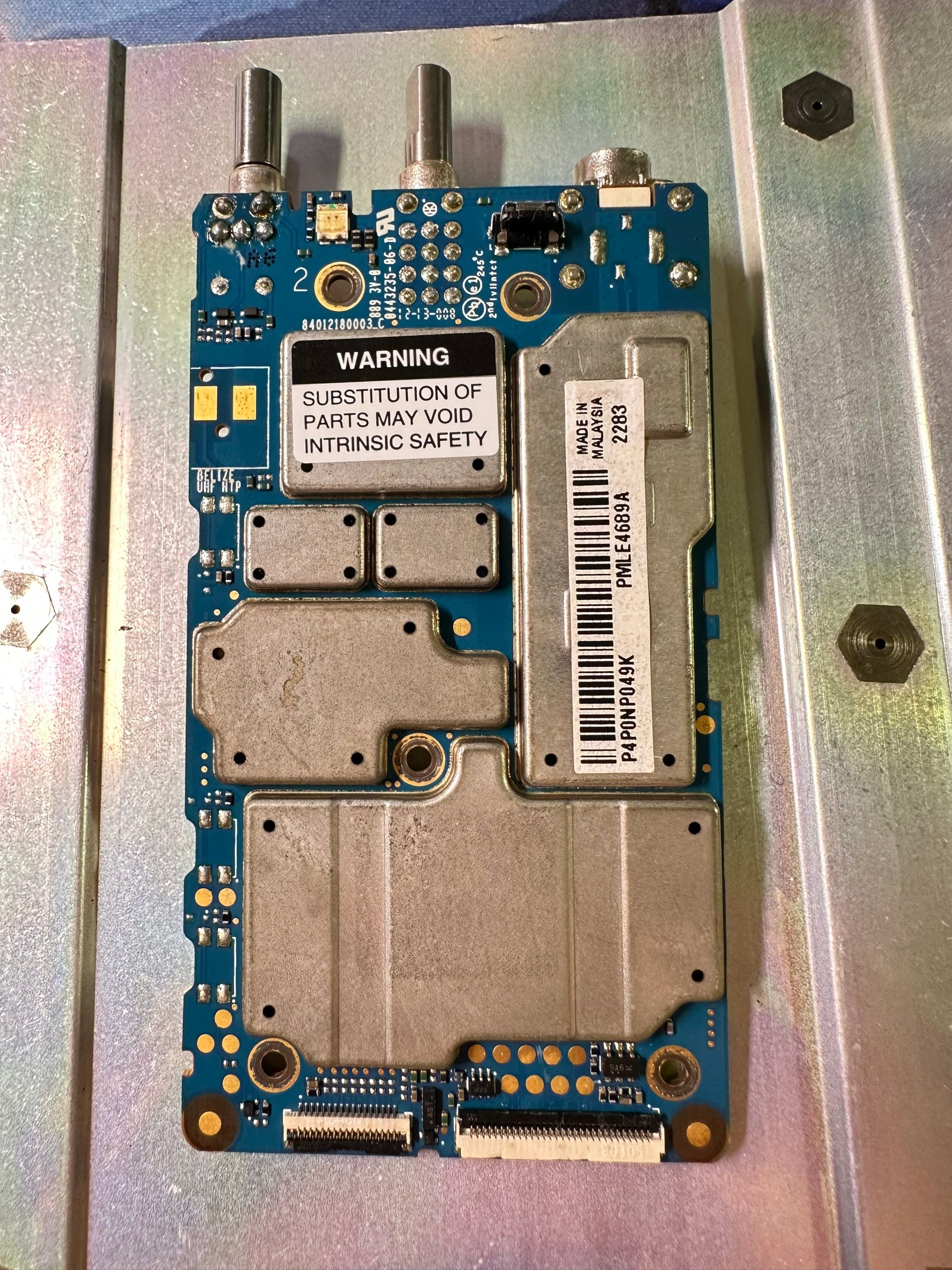
Flip it over and it’s more shield cans. Down at the bottom are two FPC connectors — one goes to the voice encryption module, the other links up the front panel: buttons, display, speaker, all that stuff.
Analysis
This board brings together three main sections: the top handles the RF RX front-end with antenna connectors, filters, and LNA for receiving signals; The right side has ceramic filters, could be narrow band if filters. You can see there’s a lot of DC-DC converters on this side; and the bottom runs an CACAP microcontroller thing. That NXP chip is SA58637, an audio amplifier handling speaker.
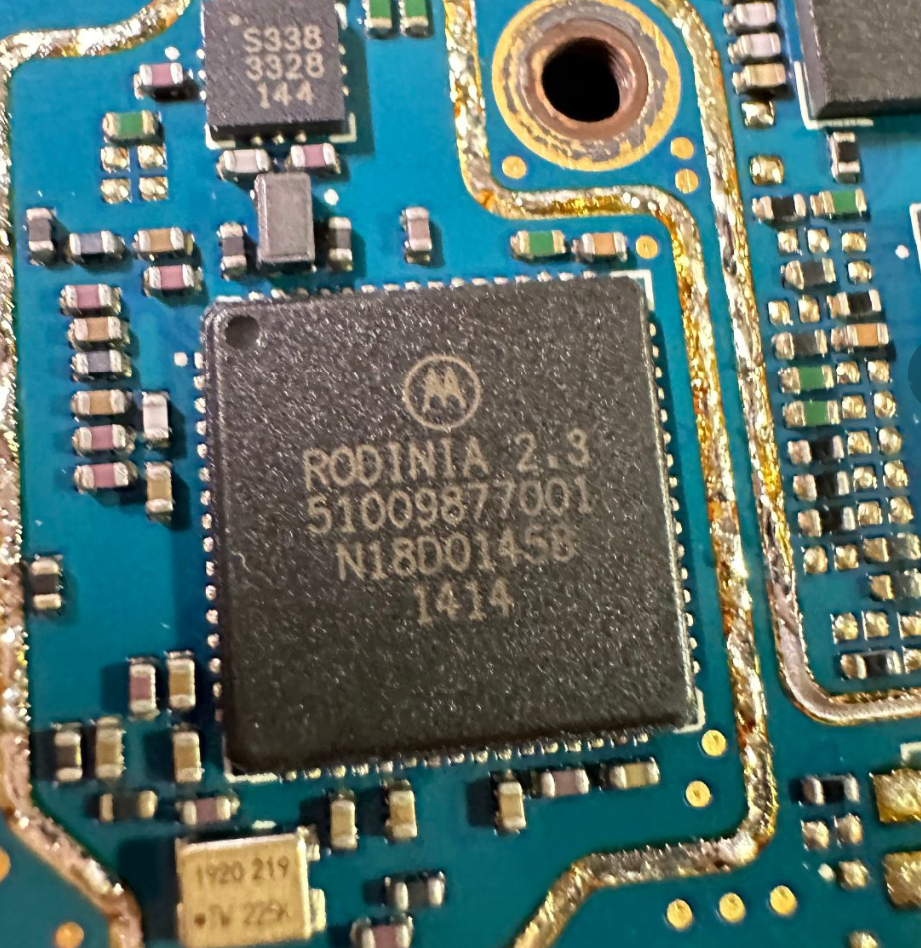
This side of the board is the digital core of the radio. At the center is Motorola’s custom RODINIA 2.3 baseband processor, which handles voice coding, channel decoding, encryption, and protocol operations. Next to it is a TI OMAPL DSP/ARM processor paired with external memory (DDR and NAND), providing the system’s computing power and storage for firmware and runtime data. My friend said this processor is pretty common in old NOKIA cellphones. Yeah, before MTK exist, they use a lot of ti processors.
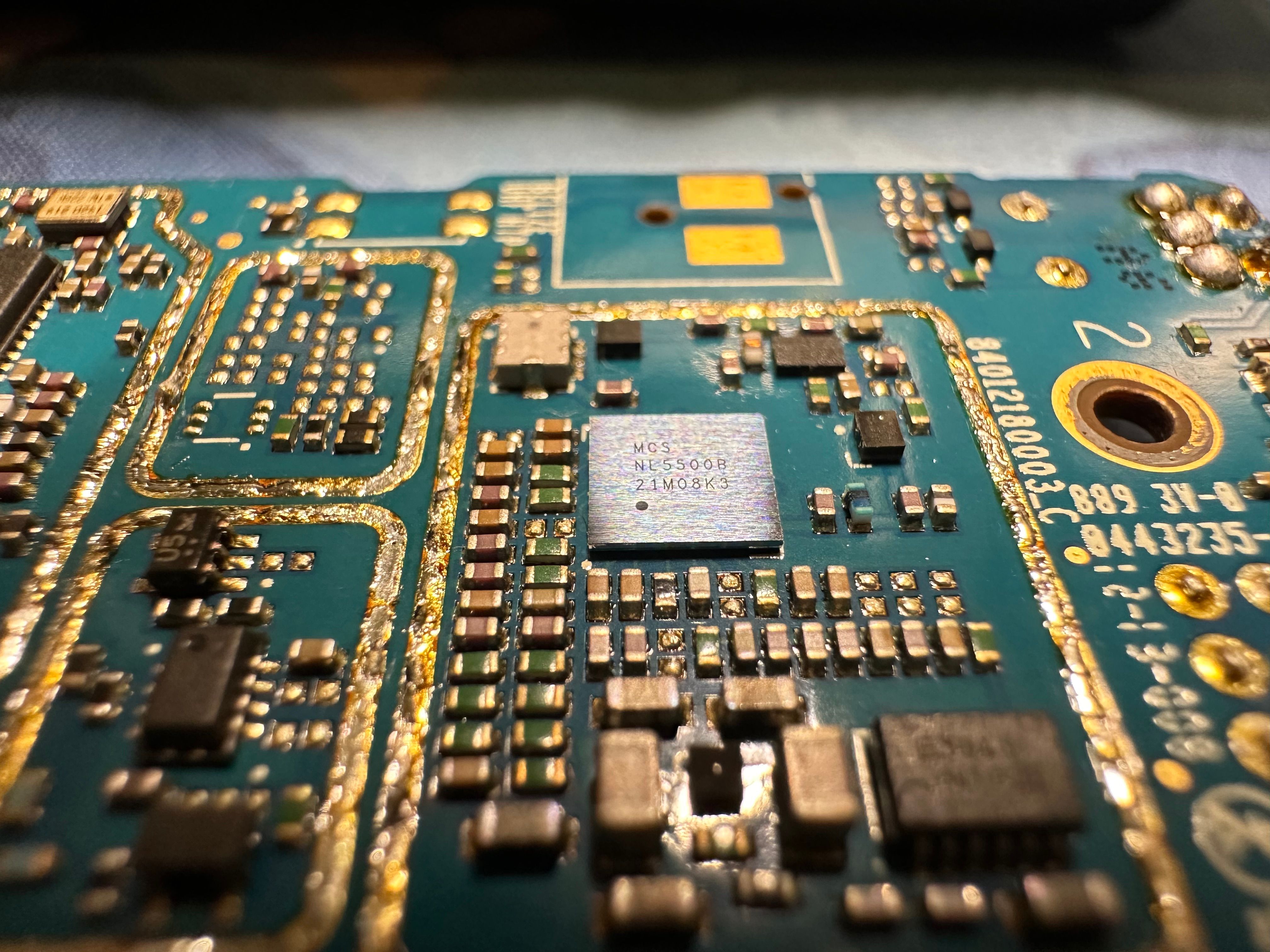
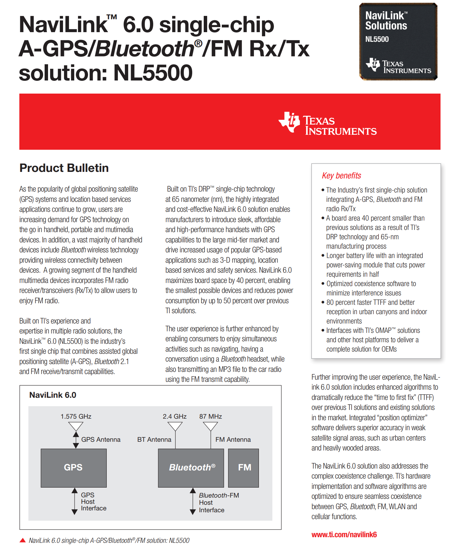
That WLCSP package chip is TI’s NaviLink NL5500.
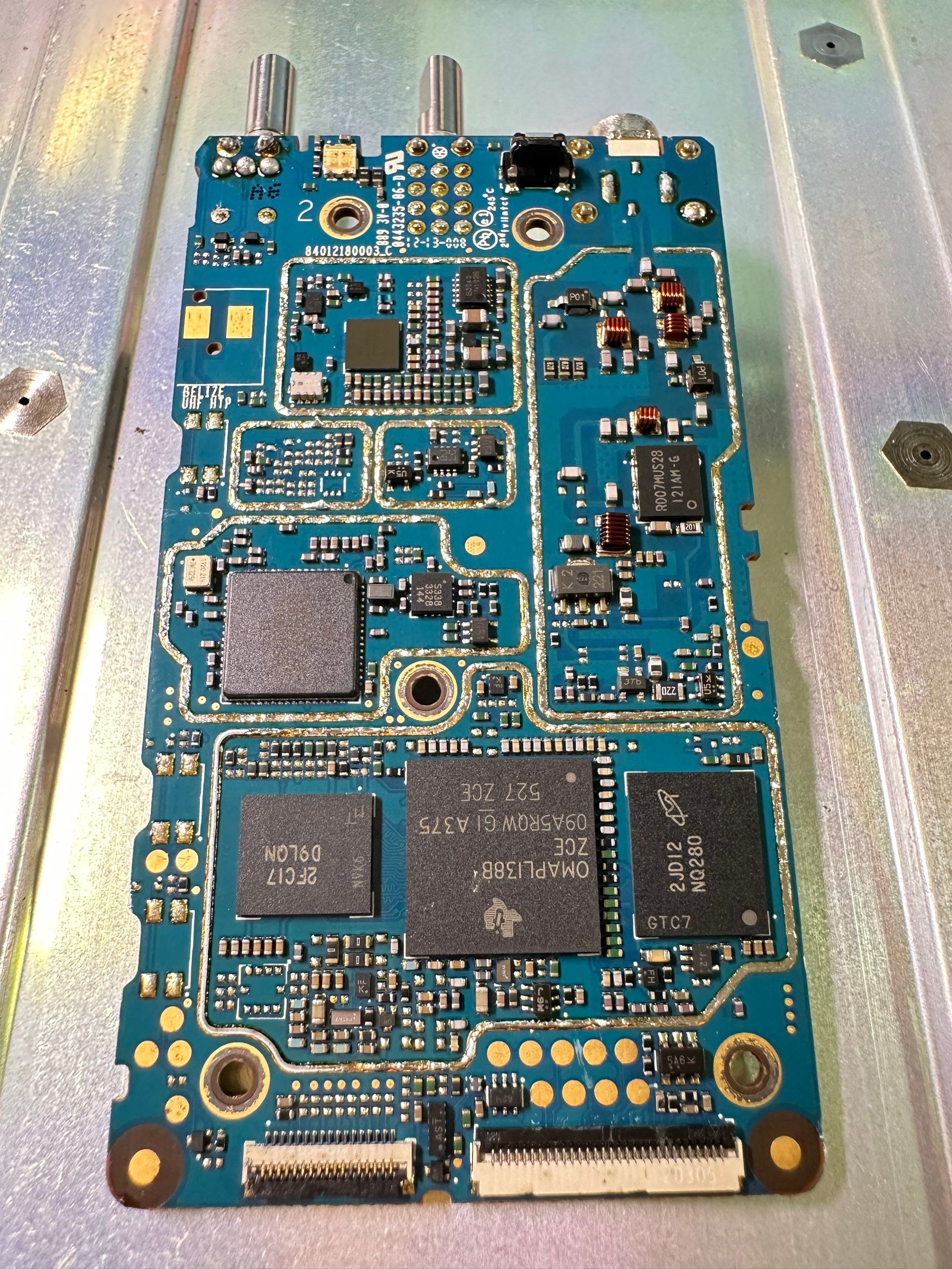
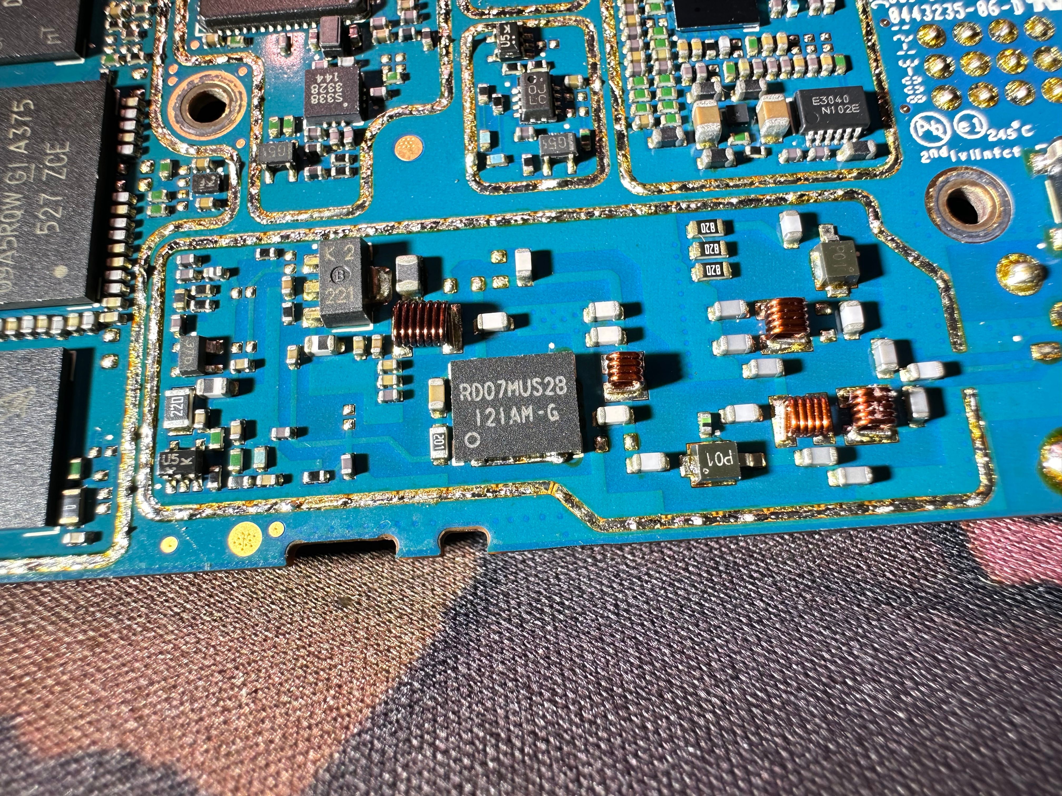
The PA section uses a two-stage design: a RD01MUS1 transistor works as the driver, boosting the low-level RF signal to a level that can drive the final stage, while the RD07MUS2B transistor serves as the main power amplifier, delivering up to 7 W of output (actually 4W max). Matching networks and low-pass filters surround these stages to ensure efficient power transfer and clean output, while bias and power control circuits keep the transmitter stable and within regulatory limits.
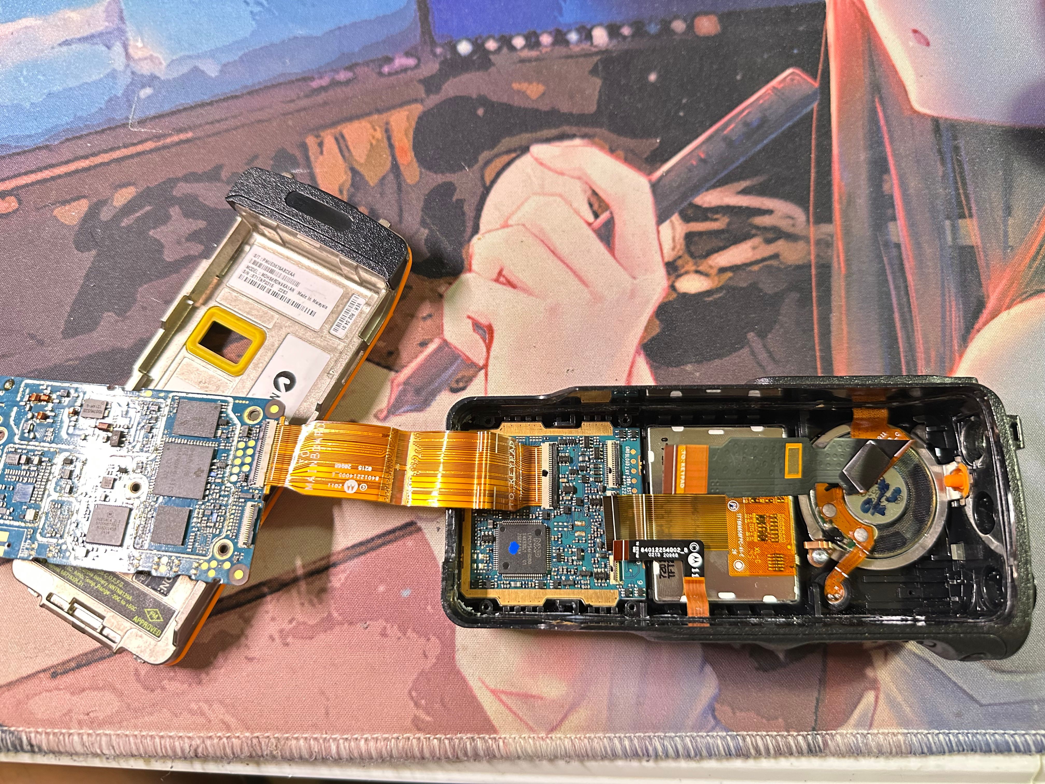
On the front side, the main board connects to the keypad board through a wide FPC cable. From there, additional flex cables branch out to the display, the data connector, and the audio module, forming the main interface between the core electronics and the user controls.
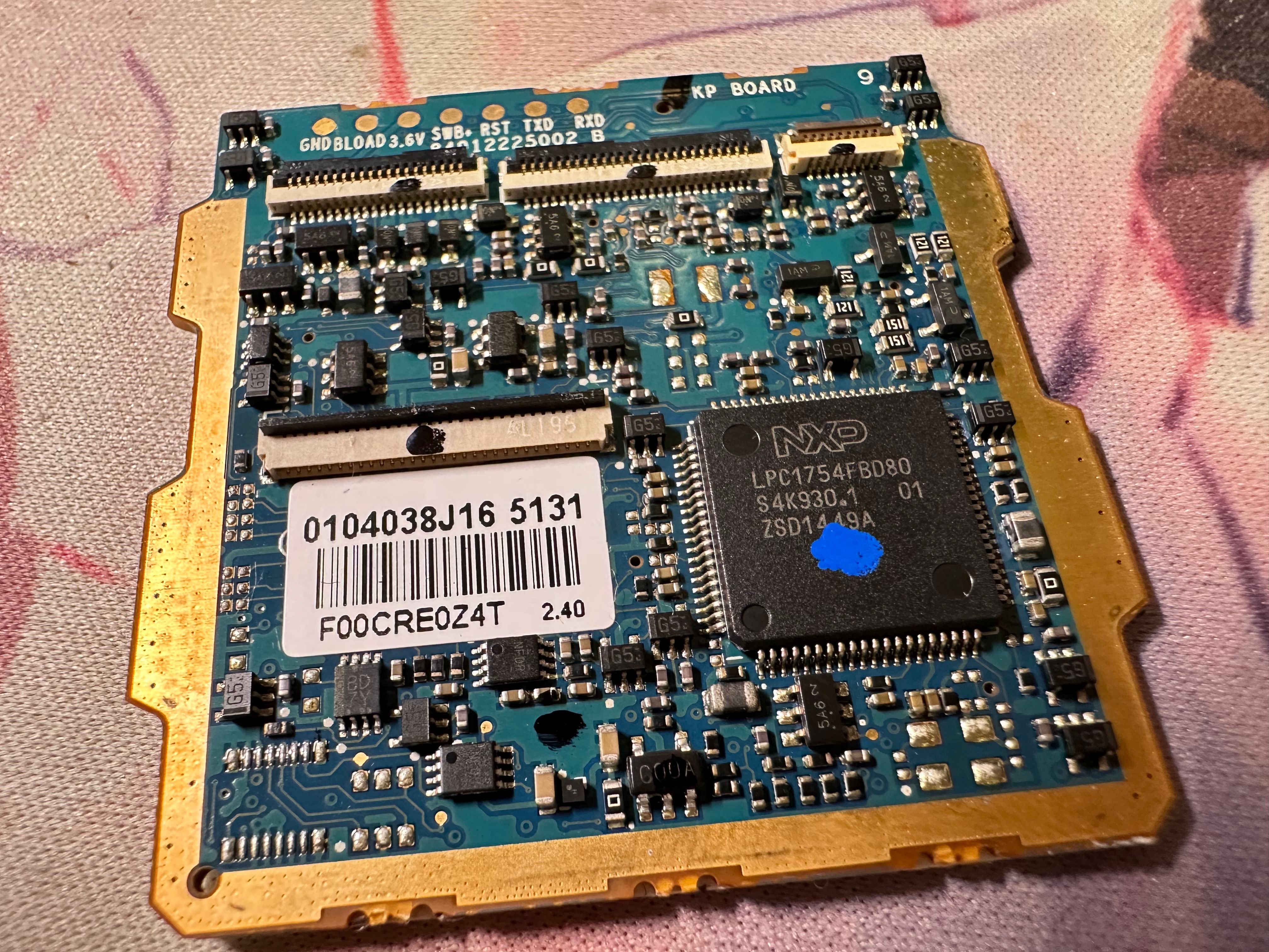
This smaller board is the keypad controller. It links the main board to the keypad, display, and audio lines through several flex connectors. At its core is an NXP LPC1754 microcontroller
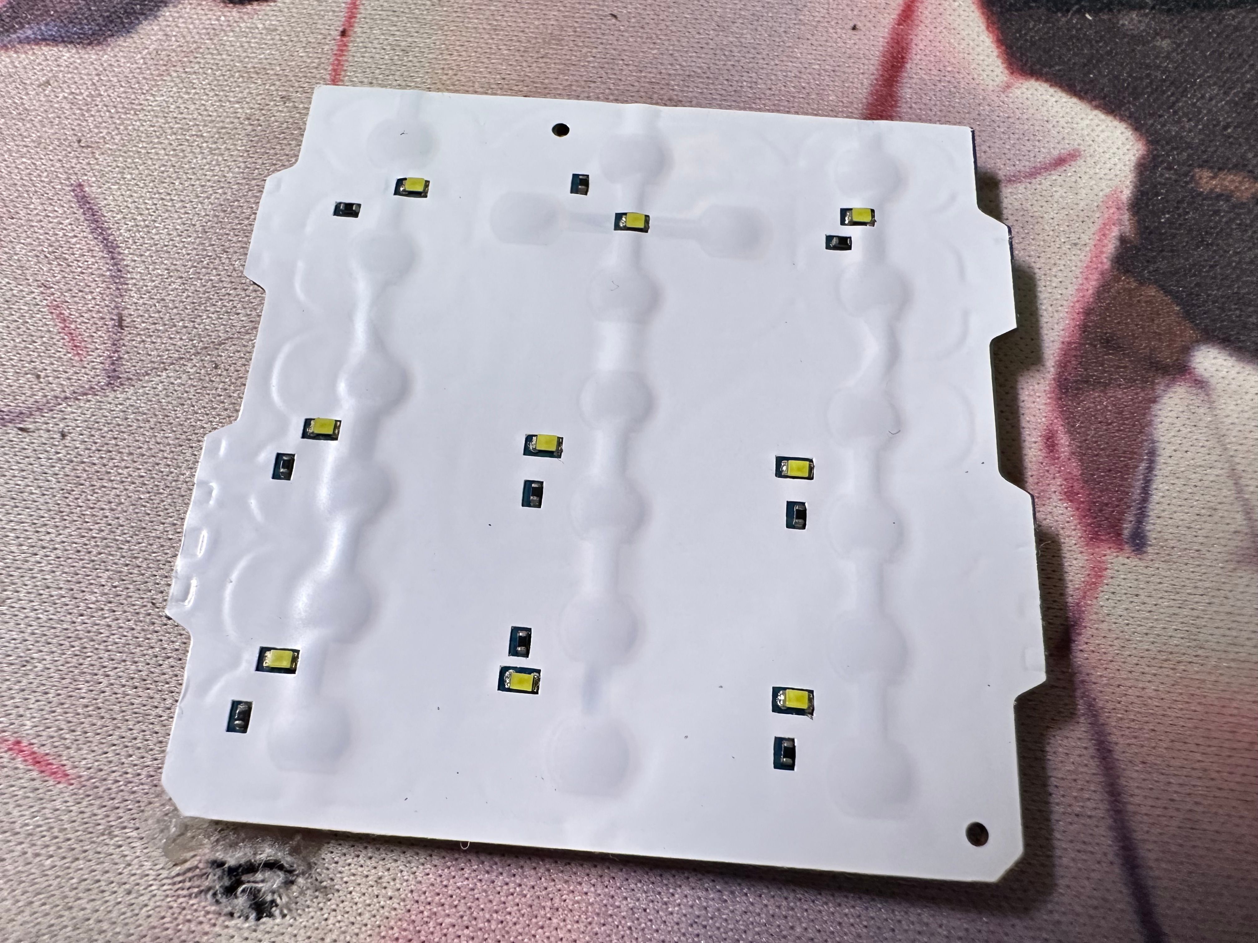
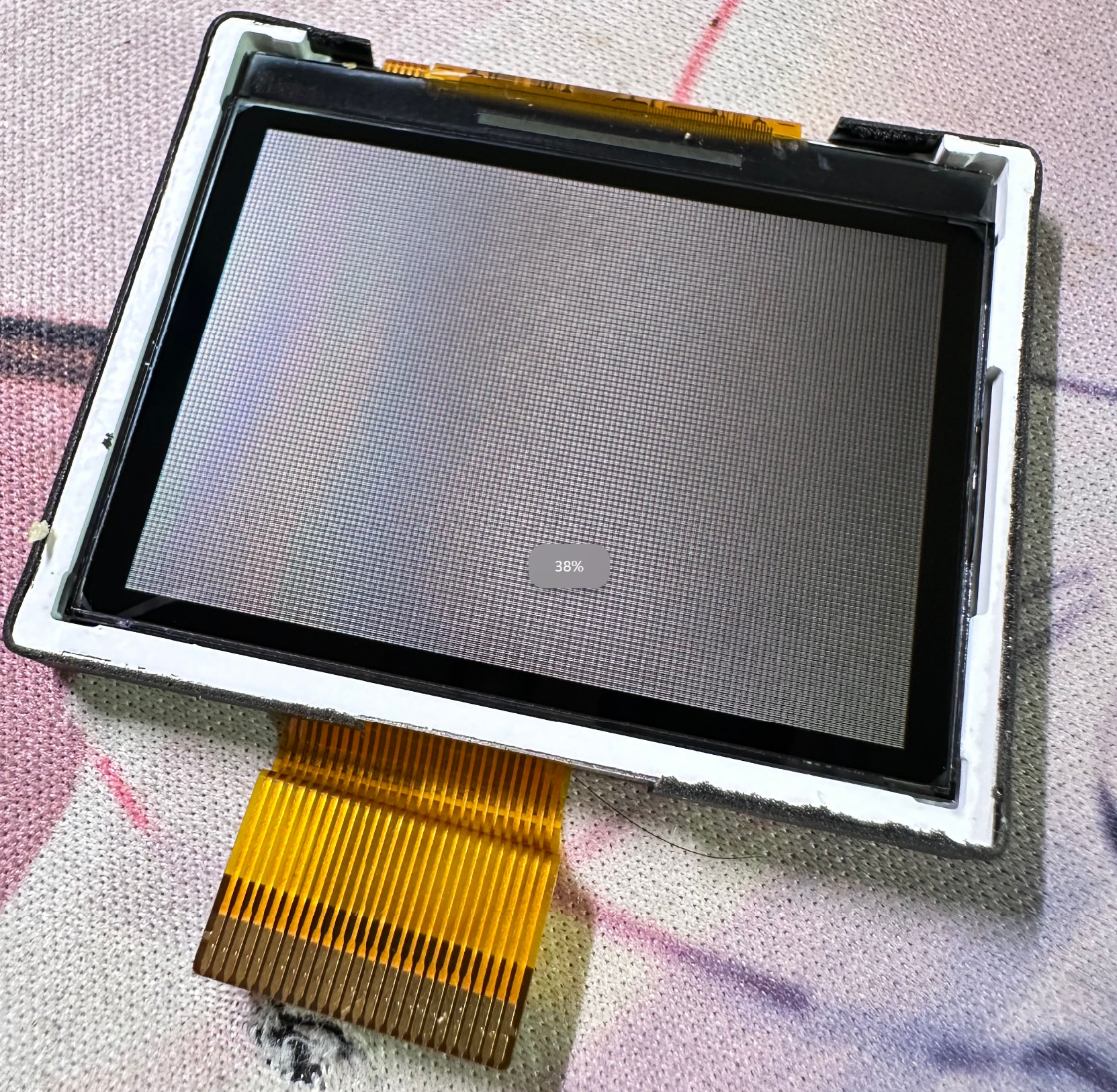
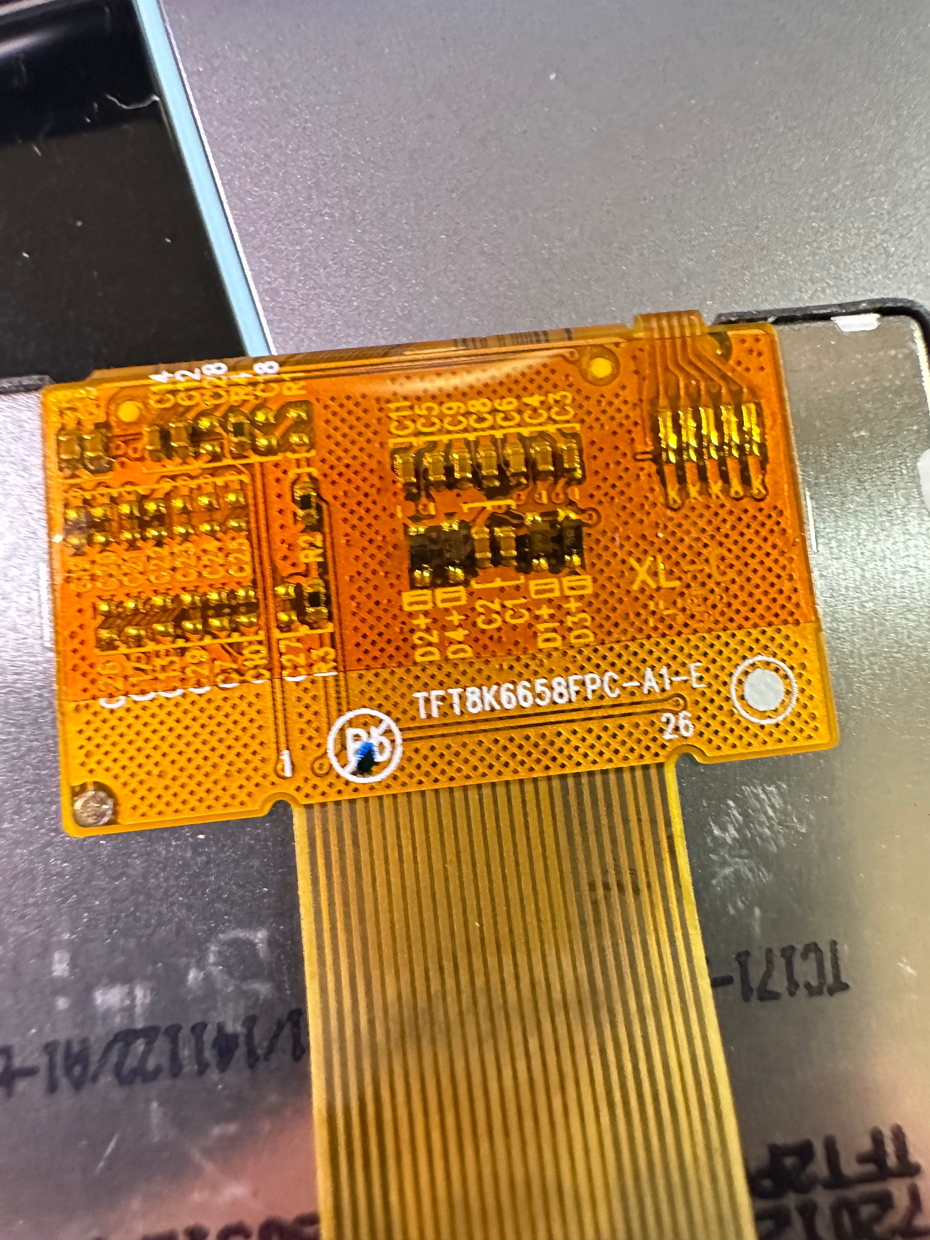
This is the radio’s display, a semi-reflective LCD with a backlight designed for outdoor readability. It’s colored. The model is TFT8K6658FPC-A1-E, providing clear visibility both in bright sunlight and low-light conditions. Beautiful.
Speaker and Mic, on the top is the data link connector
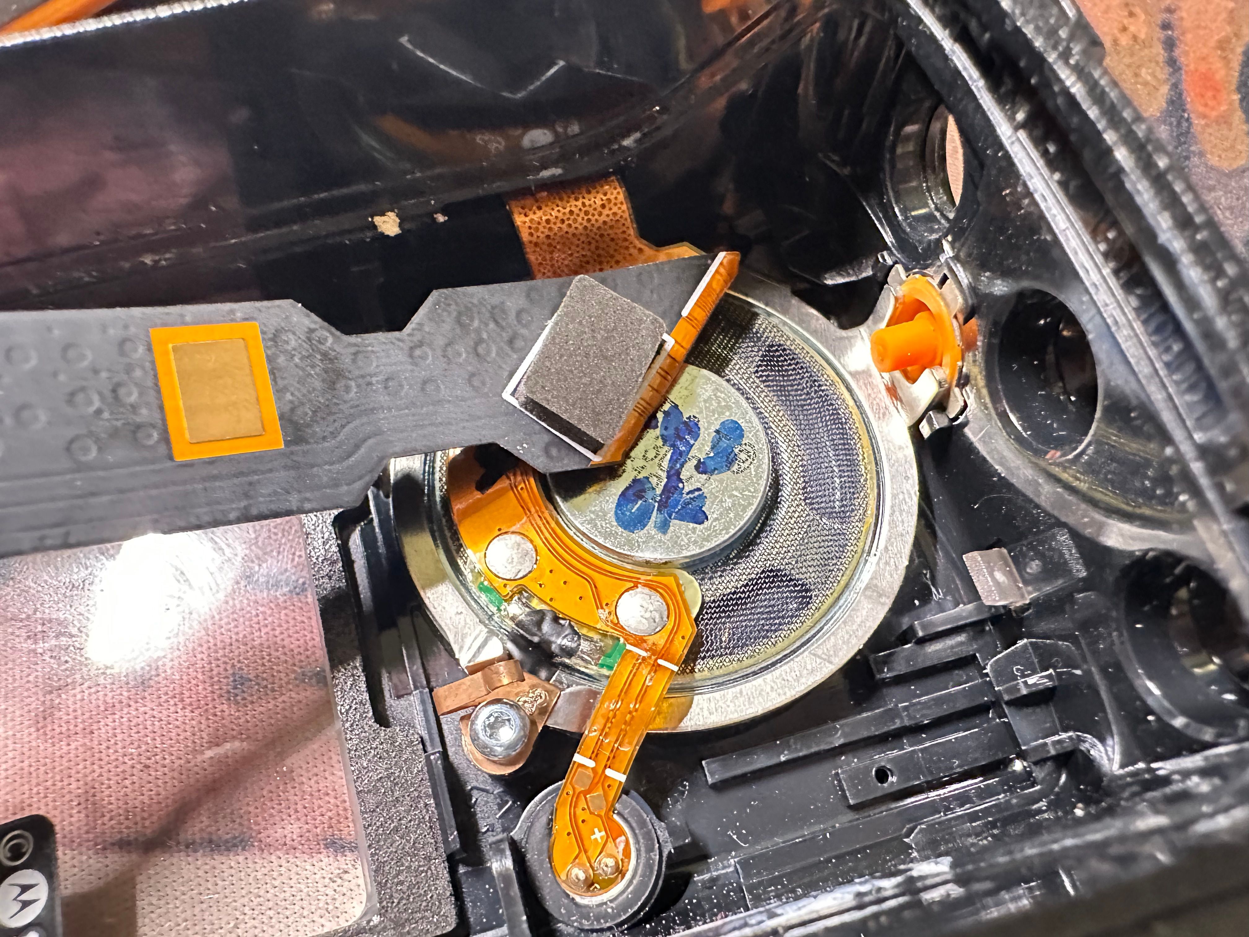
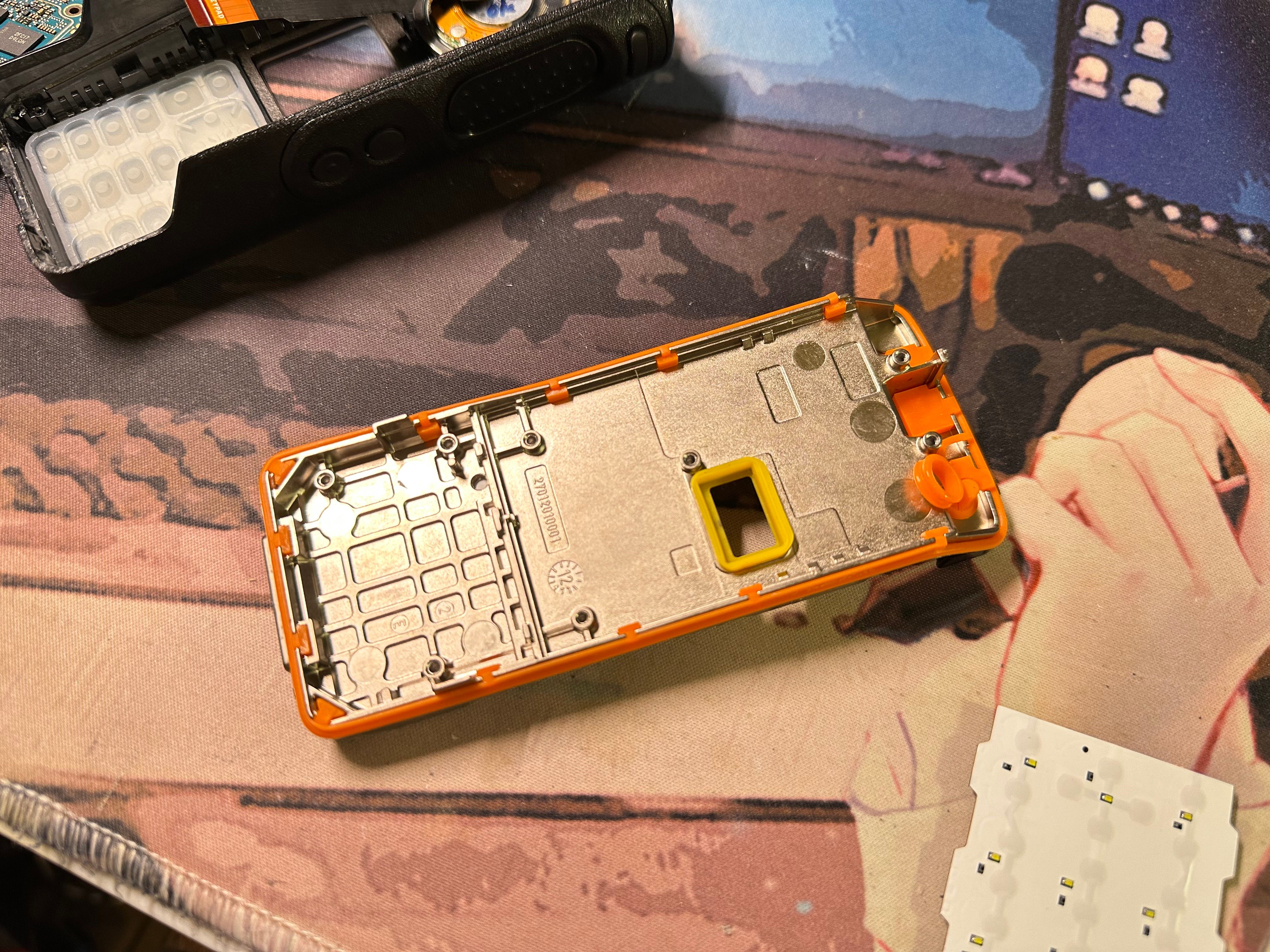
Aluminum case with nice orange rubber ring for water proofing.
Trying to fix it
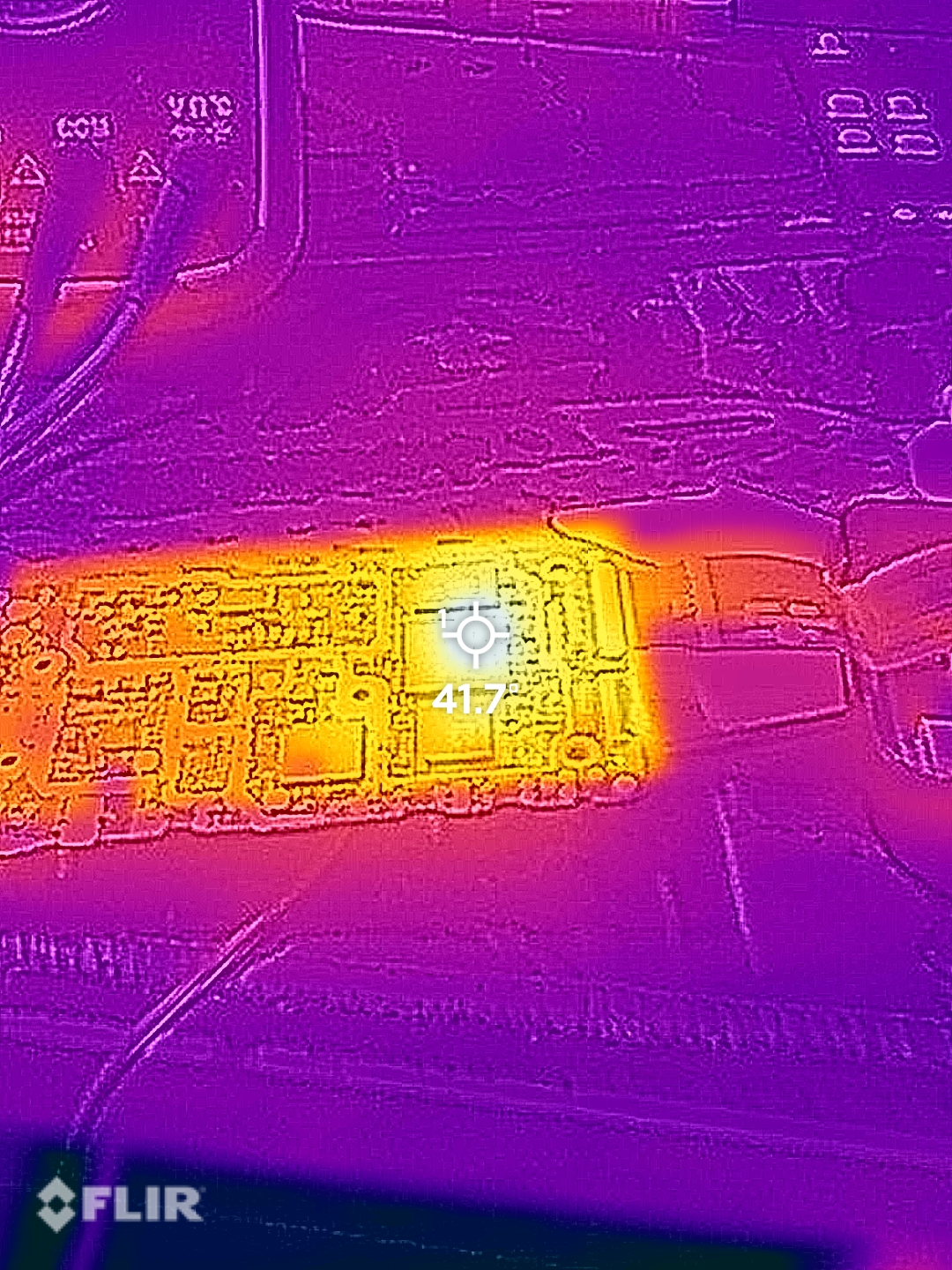
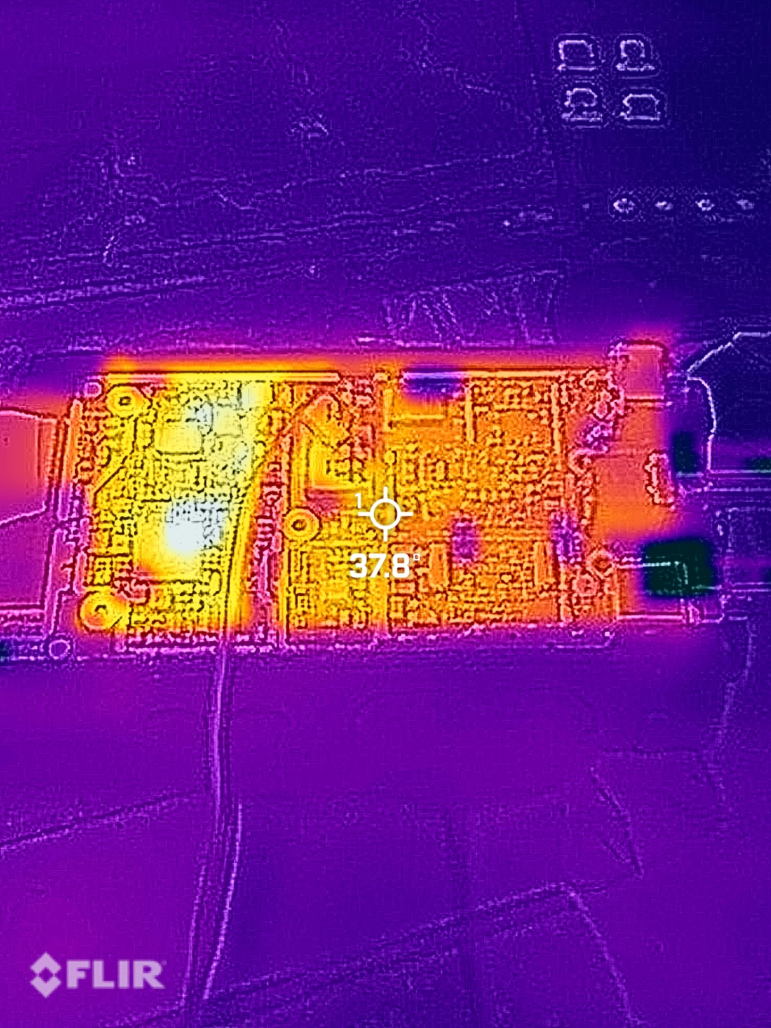
After powering it up with a bench supply at 8 V, the board drew about 100 mA. Both main controllers warmed slightly, giving the impression it was alive, but no LEDs lit up, no display response, and no reaction to the PTT or any buttons. I used multimeter to test all the inductors on both sides, and all power supplies are working and generating their voltages, it cannot be any shorts.
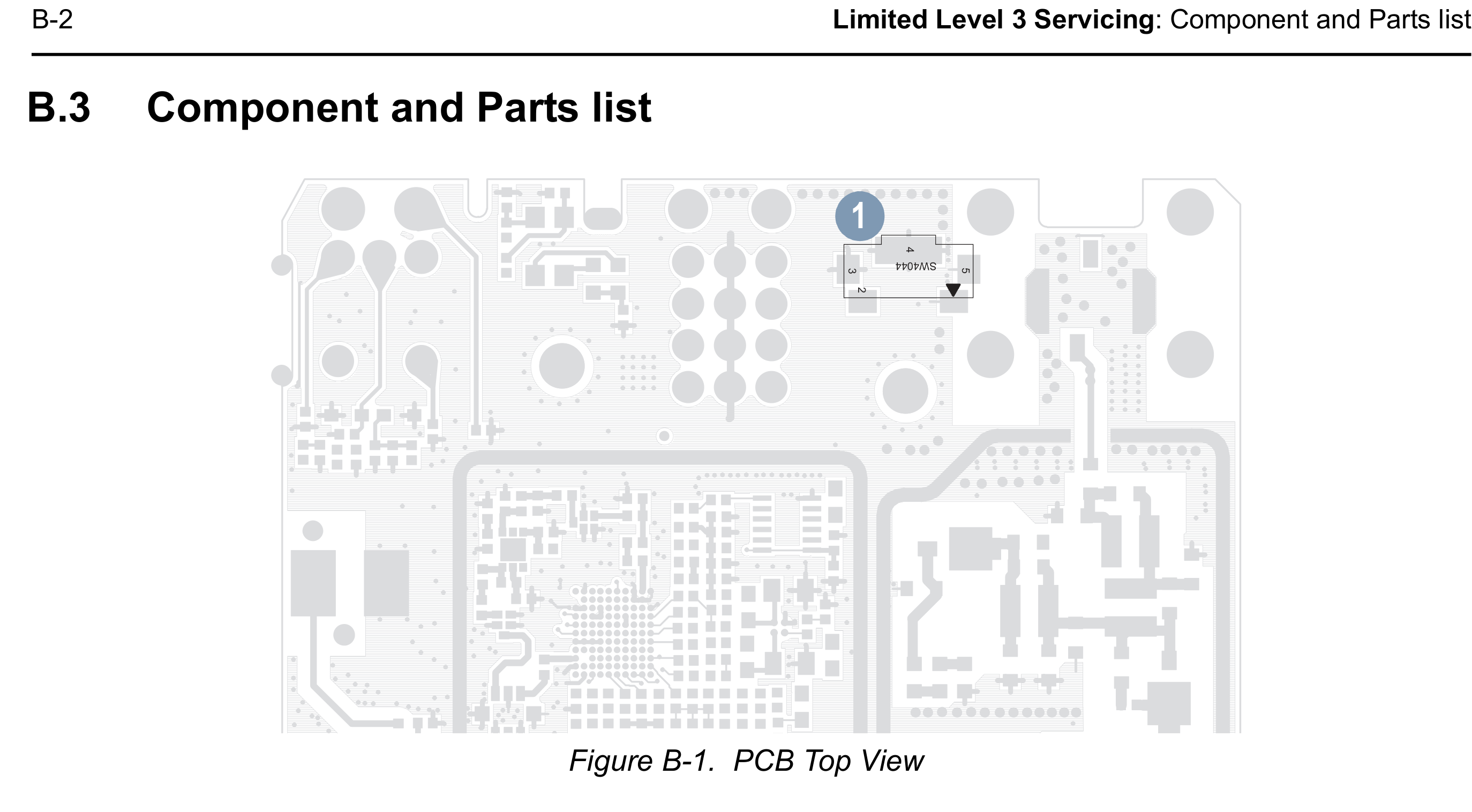
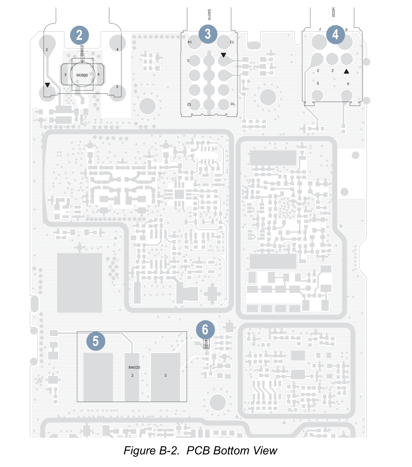
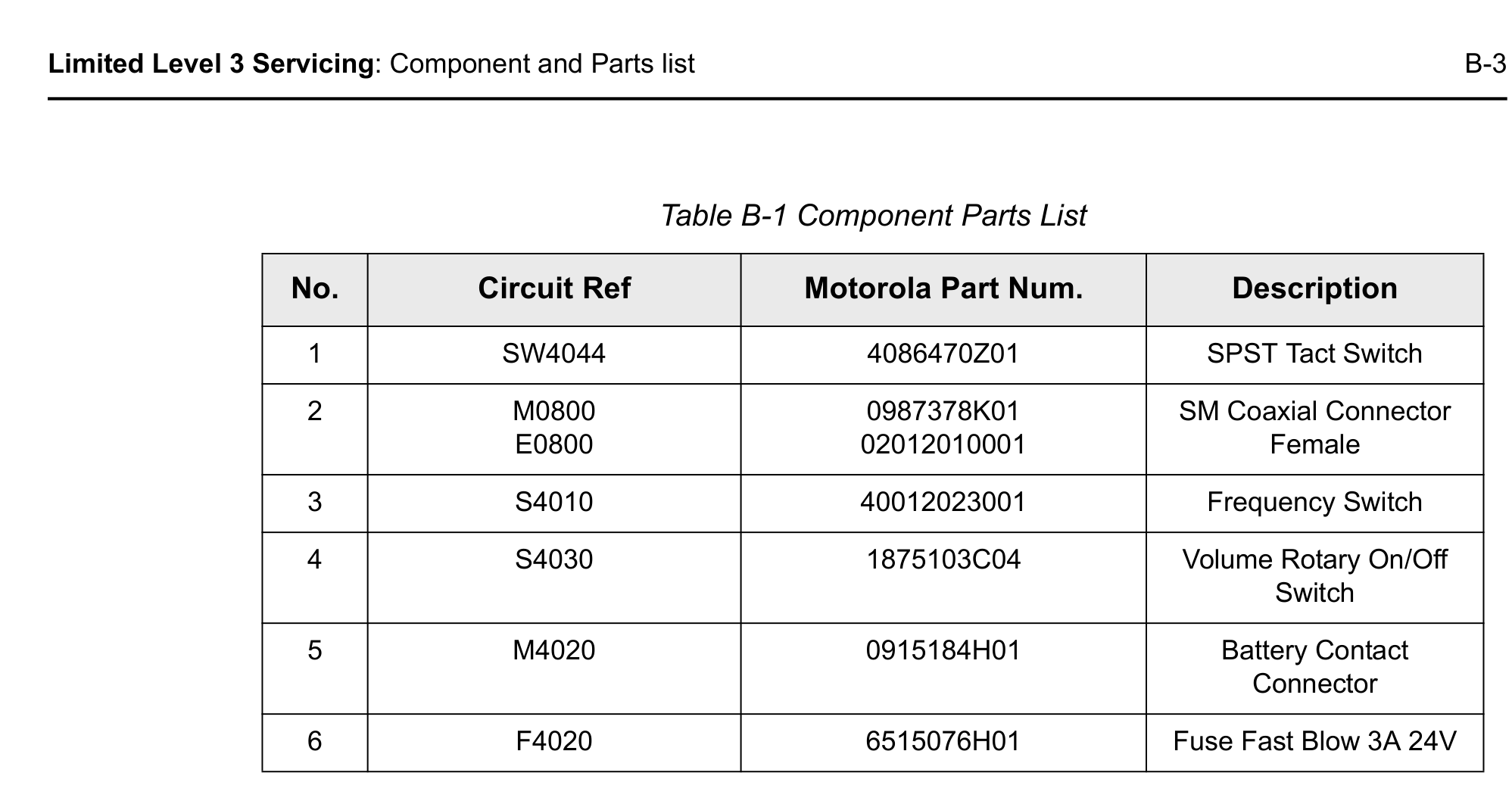
A basic service manual exists, but it offers no real help, and with so many undocumented custom chips on board, the chances of a successful repair are close to zero. So at this point, it’s safe to call it a day.
it even has part of PCB top layer routing pictures, but just partial. That’s for you to replace the knobs or buttons, rather then repair it.
Conclusion
This teardown shows how the radio is built around two major domains: the RF front-end, with its power amplifiers, filters, and matching networks that move signals in and out of the air, and the digital core, centered on Motorola’s custom RODINIA 2.3 baseband and a TI OMAPL processor running all the coding, protocols, and control logic. Supporting boards like the keypad controller with an NXP MCU and the semi-reflective TFT display complete the user interface. Together, these modules highlight the mix of rugged RF hardware and powerful digital processing that defines a modern professional two-way radio.