For couple of weeks, I’ve been aiming to design and build DATV transmitters for HAM TV applications.
To send signals farther, an RF power amplifier is essential — since typical modulator outputs are only around –20 to –10 dBm. If the TX power target is 1 W, that means we need at least 40–50 dB of gain. Honestly, my knowledge of RF PAs is limited, and due to radio regulations, it’s not easy to access high-power RF amplifiers. I’ve built HF PAs before (<30 MHz, SSB mode), but that’s quite different from today’s digital modulation challenge.
Over two days of experiments, I tested several RF power amplifiers, recorded data, and drew some conclusions. The results weren’t ideal, but the lessons learned were truly valuable.
The main purpose of my experiment was to explore the impact of RF power amplifiers on digitally modulated signals.
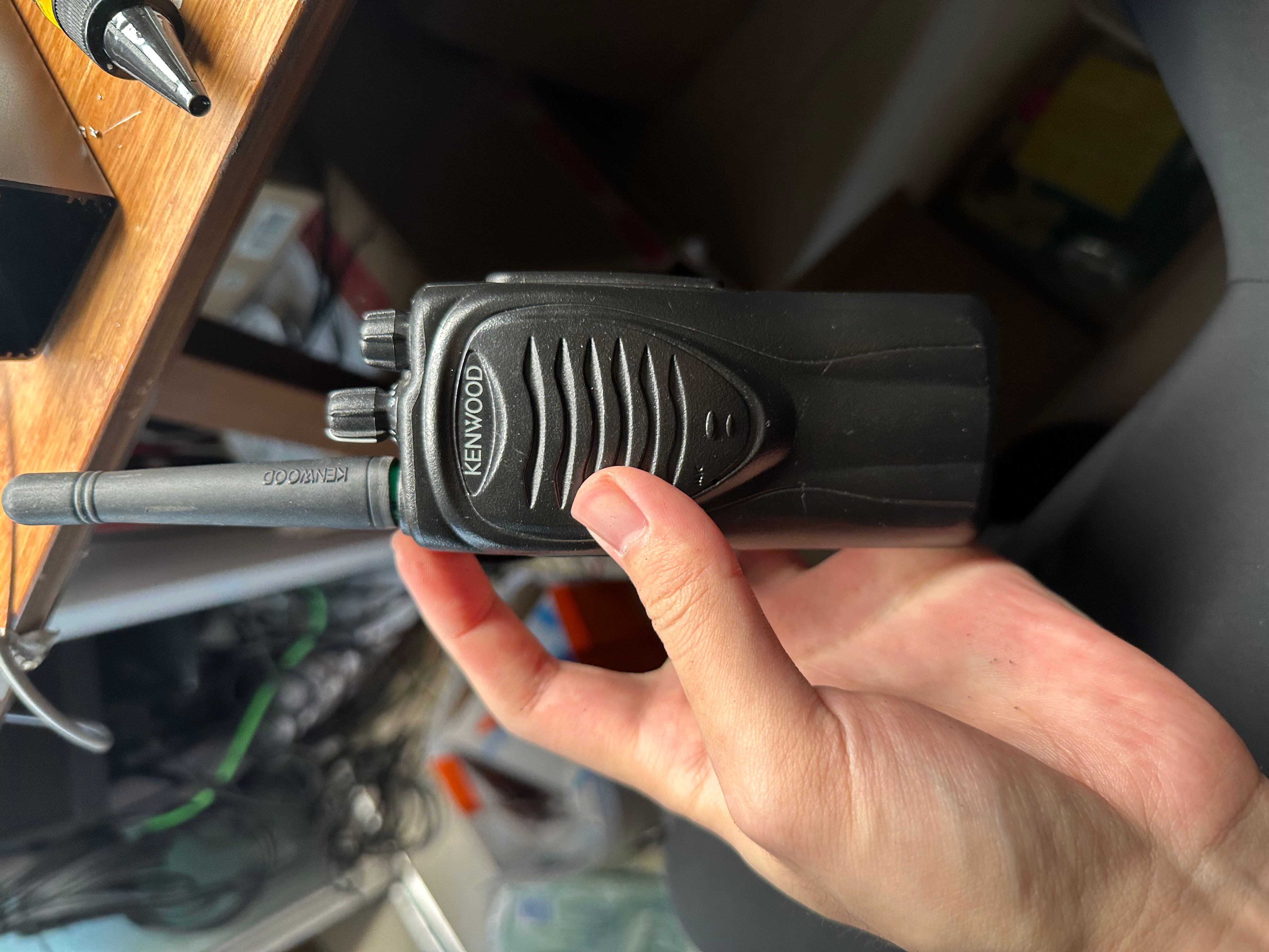
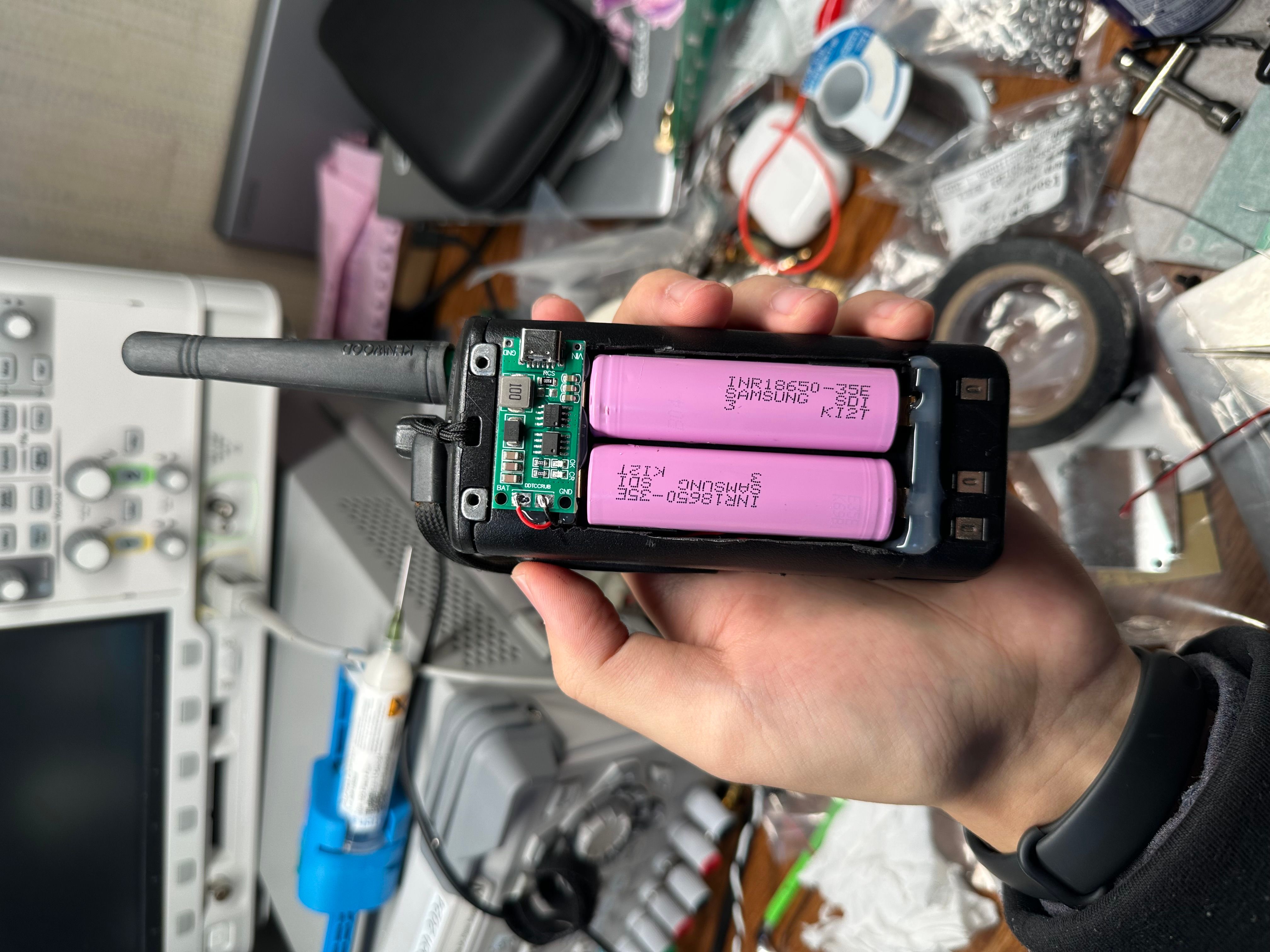
The first experiment I conducted was with my old TK-3207 walkie-talkie. To be honest, it’s not very useful anymore since it operates at 460–470 MHz as a pure FM analog mode. In Australia, this band is allocated as CB, while in China it falls under commercial radio frequencies. In either case, operating it legally requires a special license.
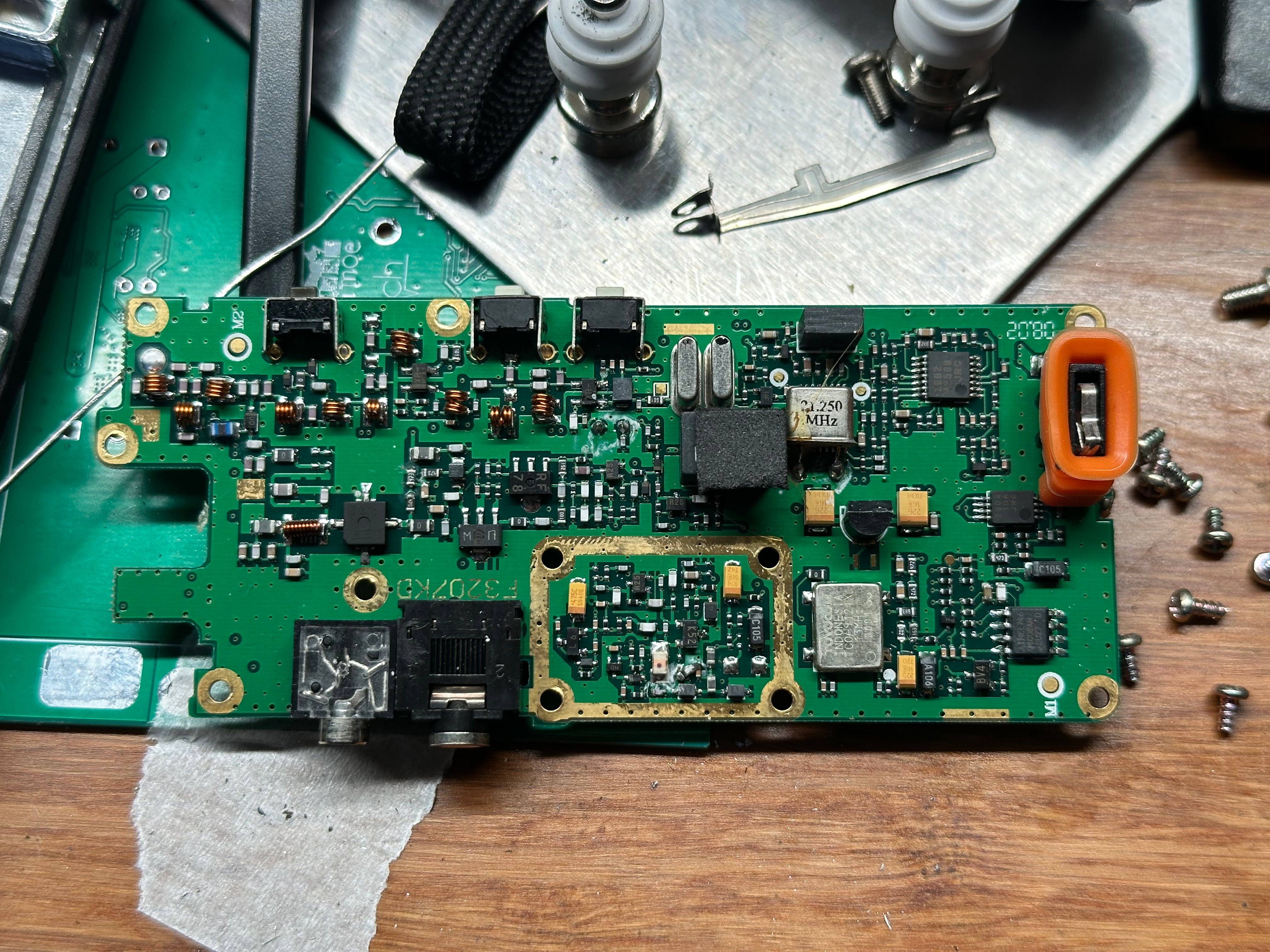
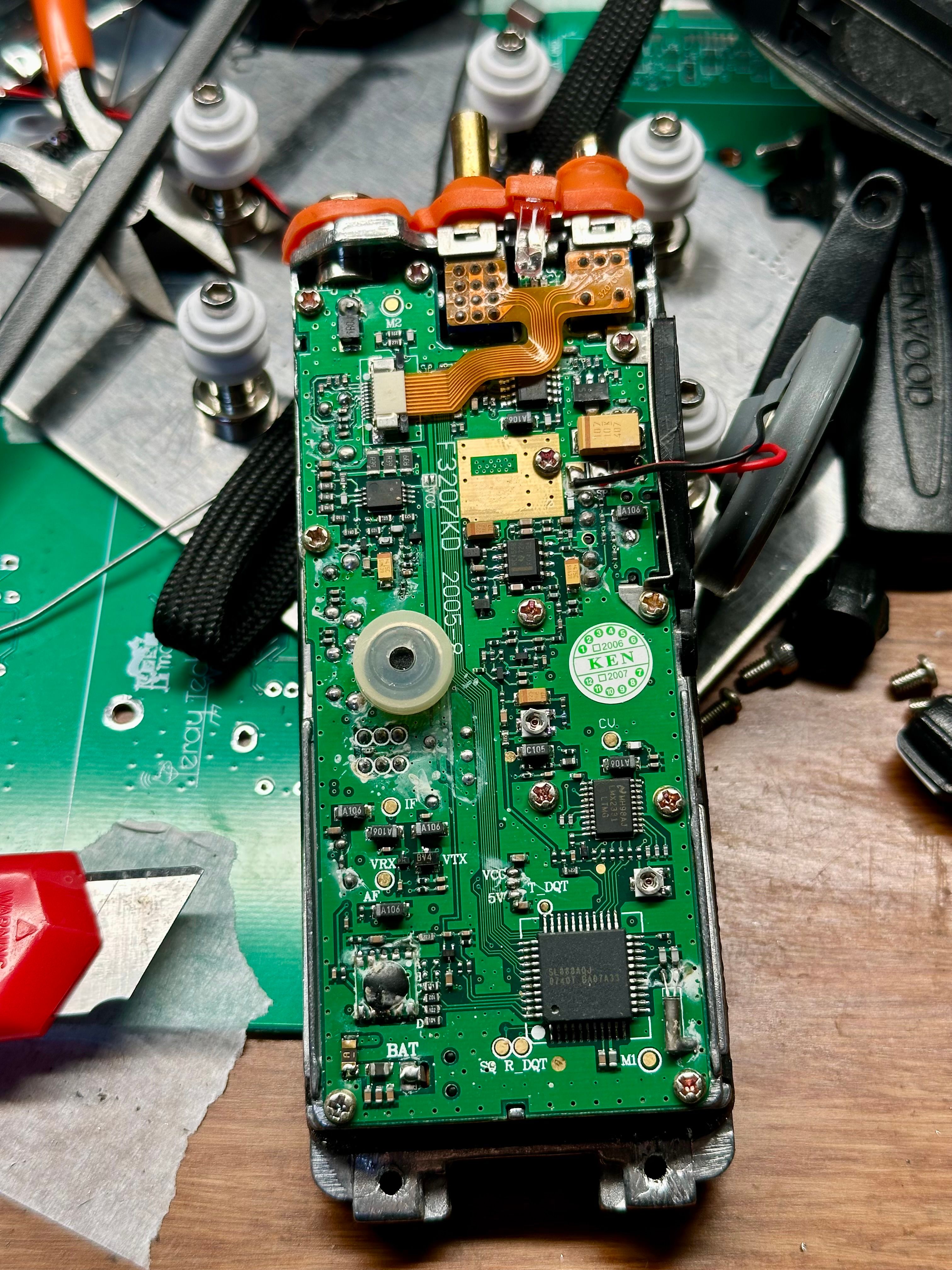
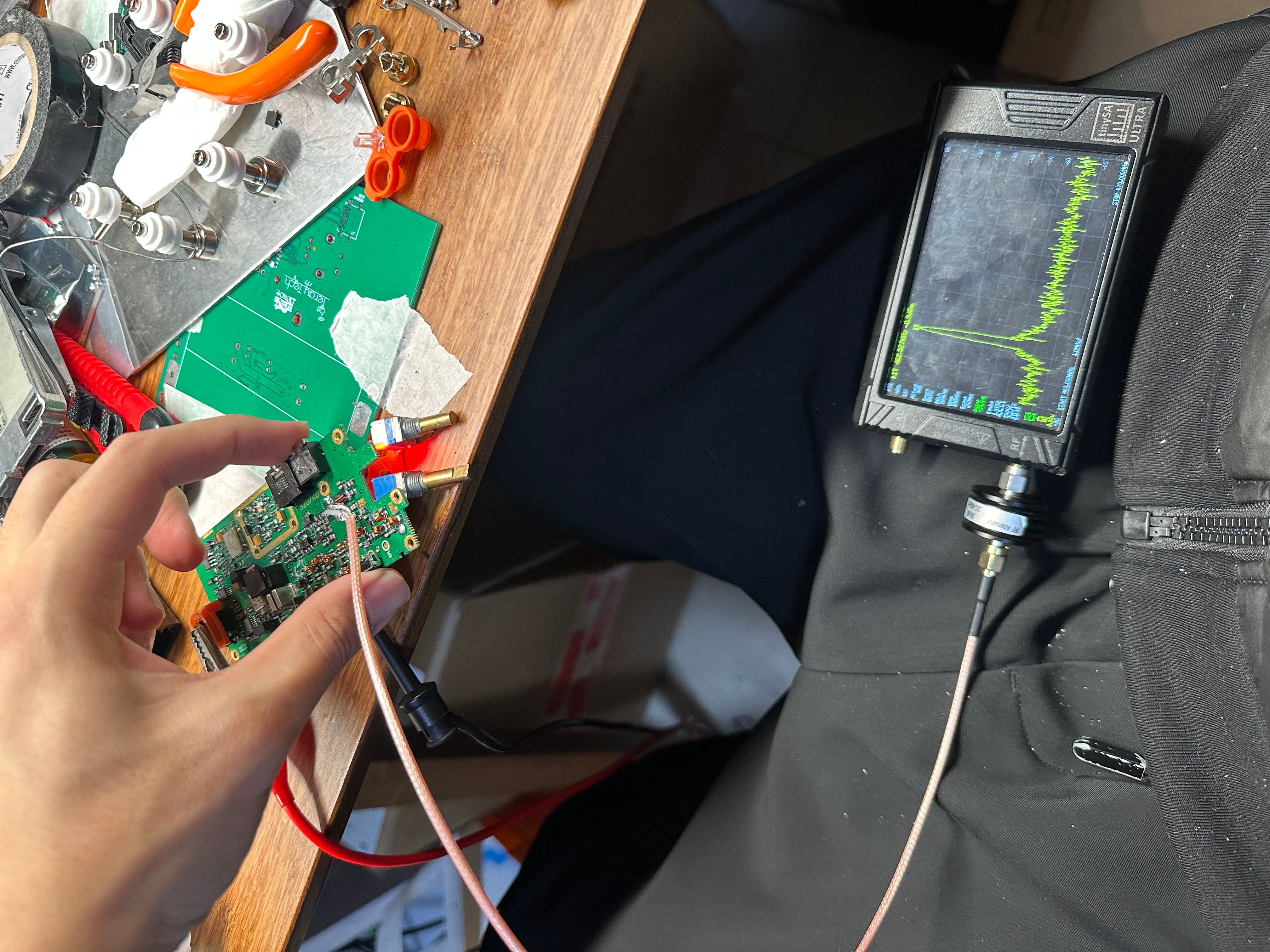
So, I disassembled it and modified the circuit, enabling me to inject my own test signal before the PA driver stage, replacing the original modulation source. The PA system in this radio is relatively complex, using multiple MOS switches to control the gate bias of the PA transistors and switch the amplifier on and off and also PIN diodes to switch between RX and TX paths. Directly injecting the signal at this stage turned out to be the simplest approach, since it bypassed the need to deal with the complicated biasing network and PIN switches.
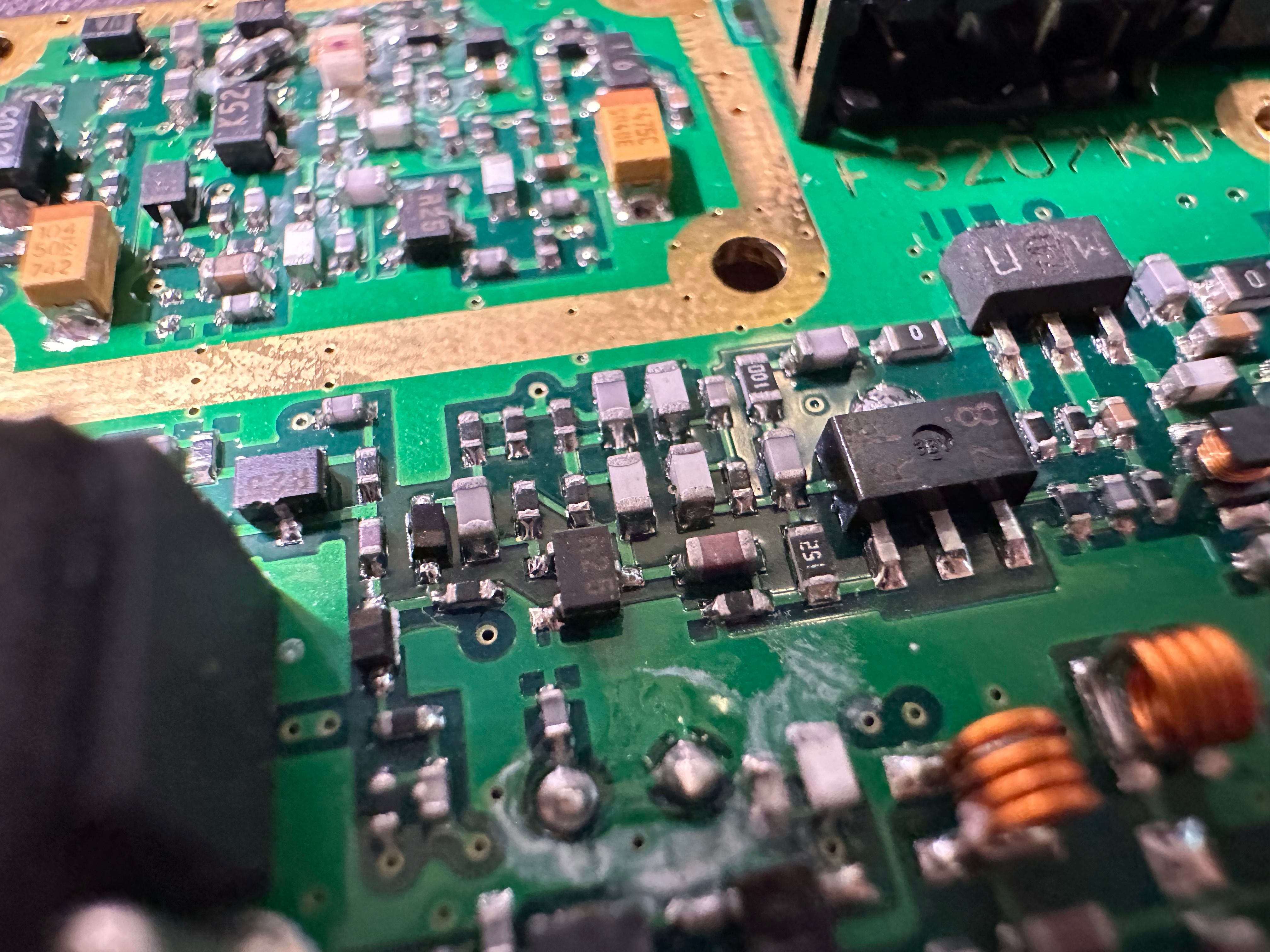
I removed several transistors and carefully soldered a U.FL gen 1 (IPEX) connector onto the PCB, making sure the coax center pin was soldered to the input capacitor of the next driver stage, and the ground was properly connected to the surrounding copper plane.
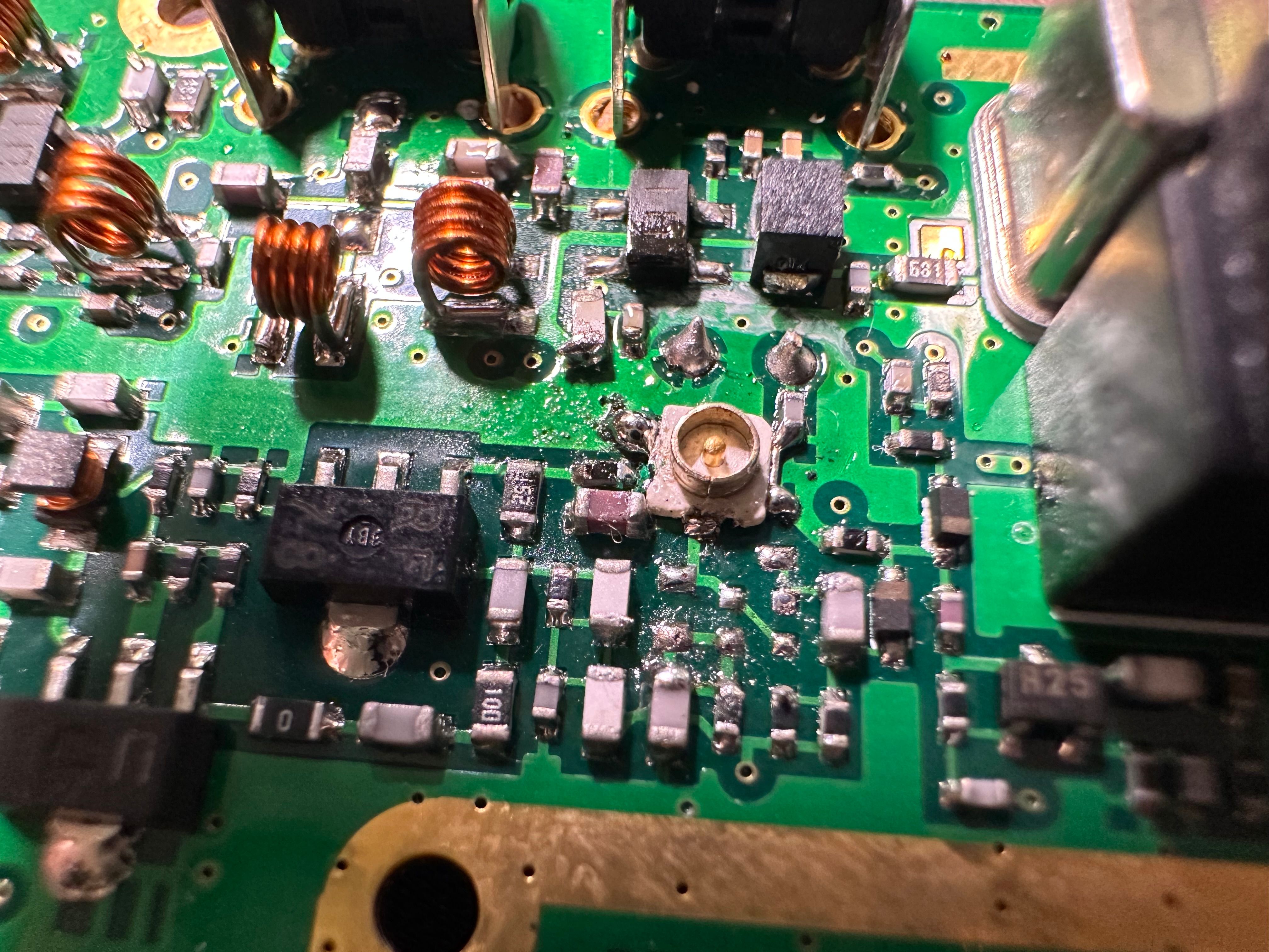
With this modification, all I need to do is play the signal from the coax and press the PTT button to enable transmission, making it extremely convenient for testing.
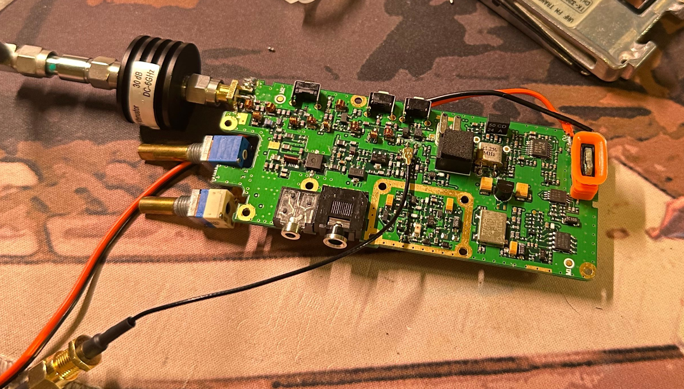
The signal source was an NI PXIe-5644R vector signal transceiver, generating a 16-QAM signal at 160 kS/s with an output level of –15 dBm, PRBS data pattern. After passing through ~40 dB of gain, the output power reached about +36 dBm, which falls right within the PA’s expected output range.
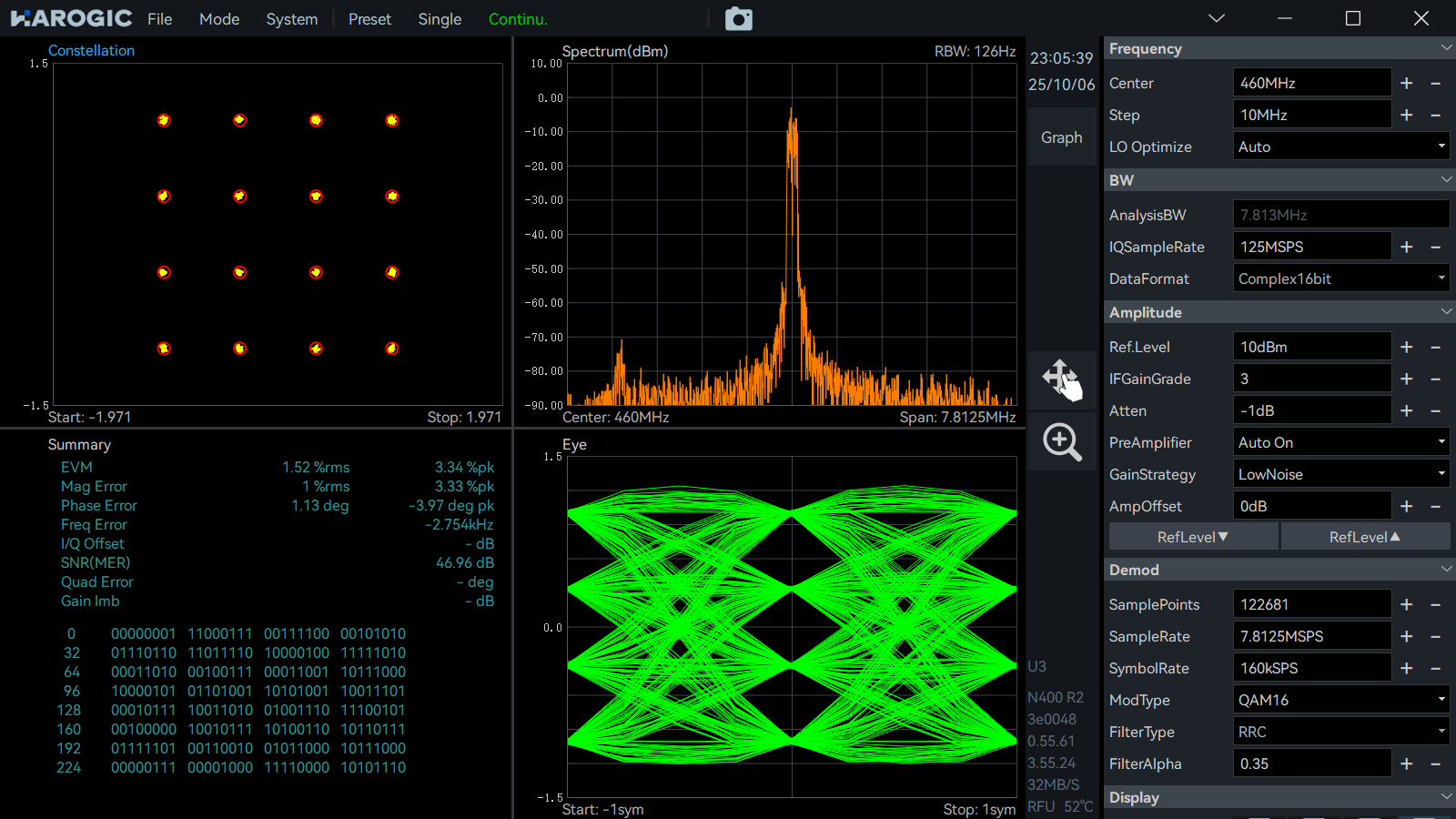
Using the digital demodulation function of the SAN-400 RTSA, the original QAM signal was demodulated and evaluated as shown below. The measured EVM was ~1%, with amplitude error of ~1% and phase error of ~1°, SNR 47dB. The constellation points were tightly clustered, the spectrum was clean, and the eye diagram was wide open and clear.
After passing through the RF PA, the output signal showed a significant increase in distortion. The EVM rose to about 11%, with amplitude error at ~9% and phase error at ~11°. The SNR dropped to 18 dB. The spectrum revealed strong intermodulation products, giving it a triangular shape. The eye diagram nearly closed, appearing highly distorted and chaotic overall.
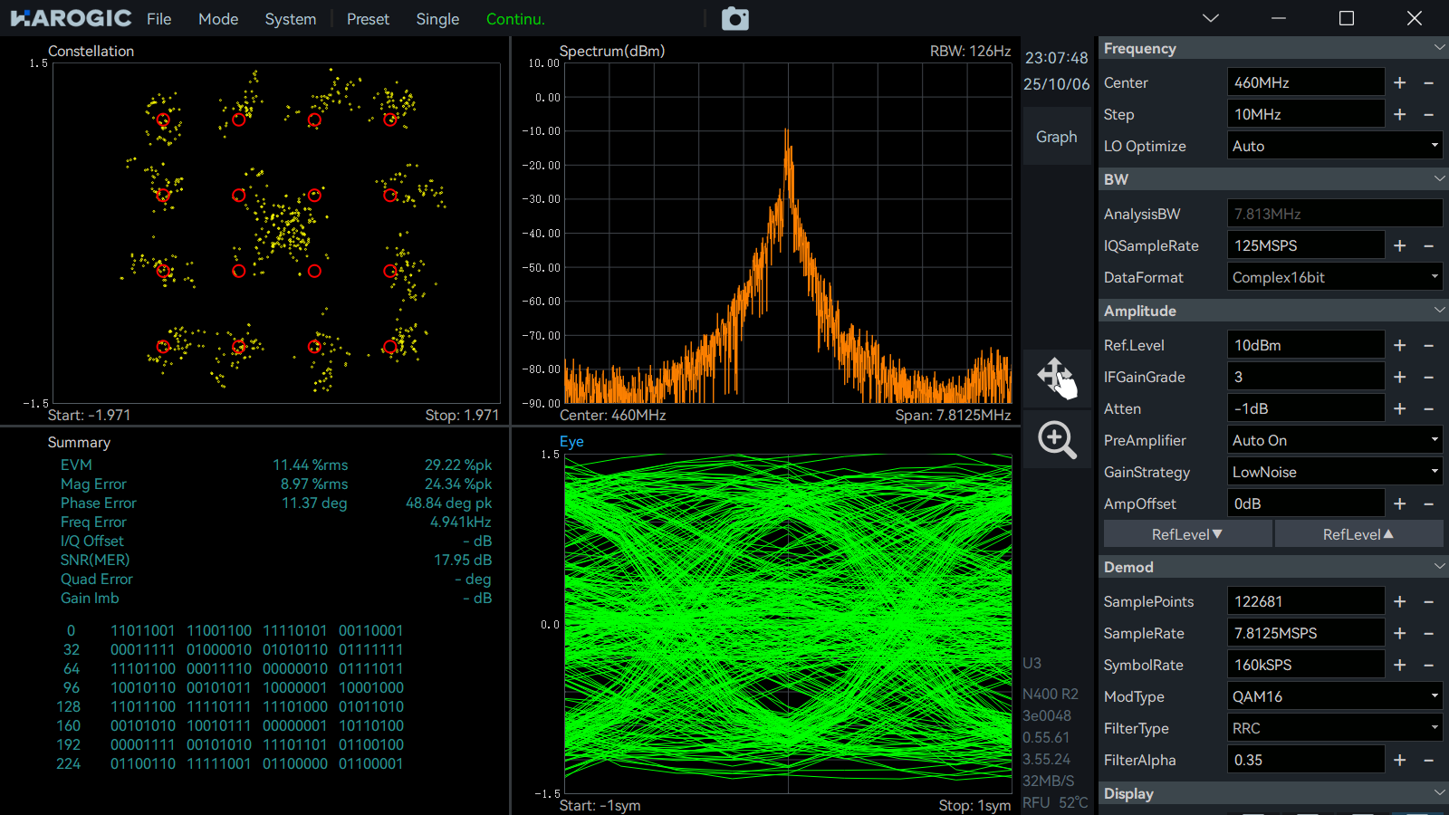
The distortion of this 16-QAM signal is primarily caused by the nonlinearity of the PA.
This phenomenon, where the inner constellation points move inward and the outer points move outward, can also occur when the low-power portions of the signal have not yet entered the amplifier’s effective operating region. In this case, the amplifier’s transconductance is not fully active, so the small-signal gain is low and the inner points are pulled toward the center. As the input power increases, the amplifier moves into its linear or even compression region, where the gain becomes higher or begins to saturate, pushing the outer points outward. As a result, the amplifier shows nonlinearity at both low and high input levels, forming an “S-shaped” amplitude response curve, and the constellation exhibits this inward-and-outward distortion pattern.
The spectrum shows broadened shoulders on both sides of the main lobe, revealing third-order intermodulation and out-of-band expansion, while the partially closed eye diagram reflects envelope distortion and inter-symbol interference. Overall, the PA is operating in its compression region, leading to significant amplitude and phase distortion. Improving linearity would require applying digital predistortion (DPD) or reducing the output power.
Actually, this phenomenon isn’t surprising. Before conducting QAM, I tested the amplifier with a single-tone signal. Even with just a pure tone input, the spectrum already showed at least 2 visible side components on each side of the carrier. This indicates that the PA introduces strong nonlinear distortion — such as intermodulation products, harmonic generation, or spurious signals — even under single-tone excitation, which naturally worsens when modulated signals like 16-QAM are applied.
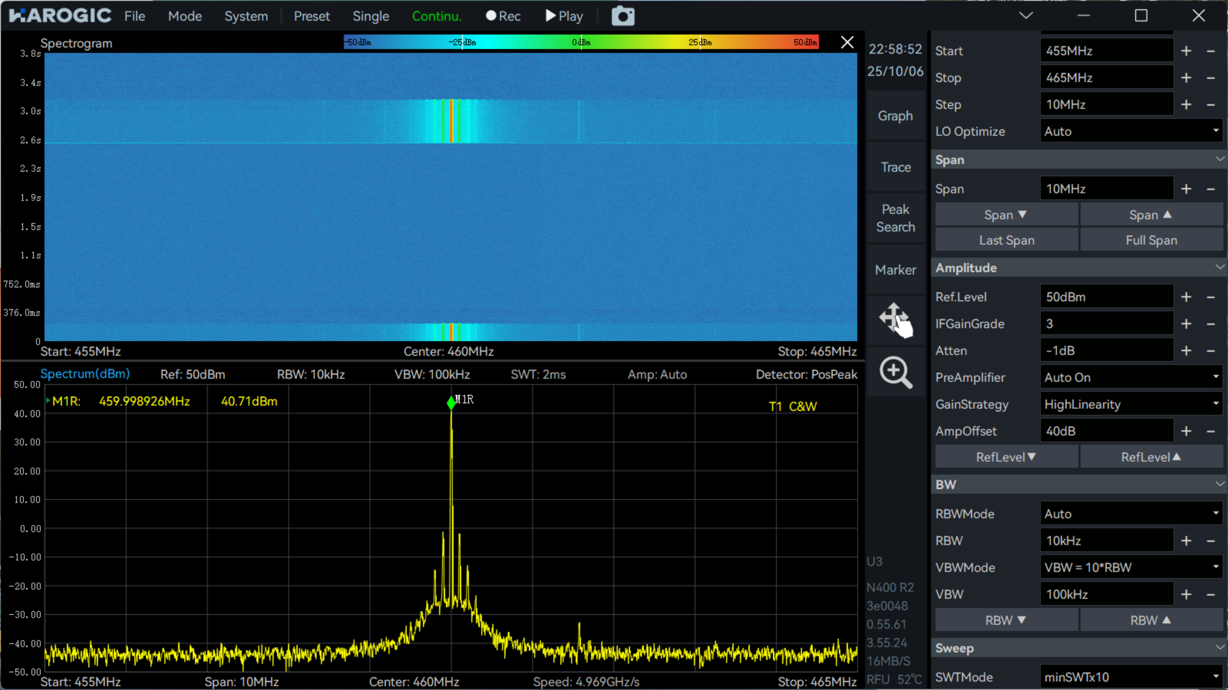
This tells us two important things:
- The PA has intrinsic nonlinearity issues. Even with a single-tone input, it generates multiple sidebands, which means the distortion is not caused by signal complexity but by the amplifier itself operating in a nonlinear region. In other words, the PA is already “dirty” without any modulation, indicating poor linearity design or improper bias control.
- Such nonlinearity becomes worse with complex modulation. When a 16-QAM or other wideband modulated signal with high peak-to-average ratio is applied, the sidebands observed in the single-tone test turn into strong intermodulation products and spectral regrowth, severely degrading EVM and MER. Thus, the single-tone test serves as an early warning — this PA is not suitable for linear modulation unless output power is reduced, biasing is optimized, or digital predistortion (DPD) is applied.
Since the original PA clearly couldn’t handle linear modulation properly, I went back to my drawer and started digging through the other amplifier modules I had, trying to piece together a workable chain.
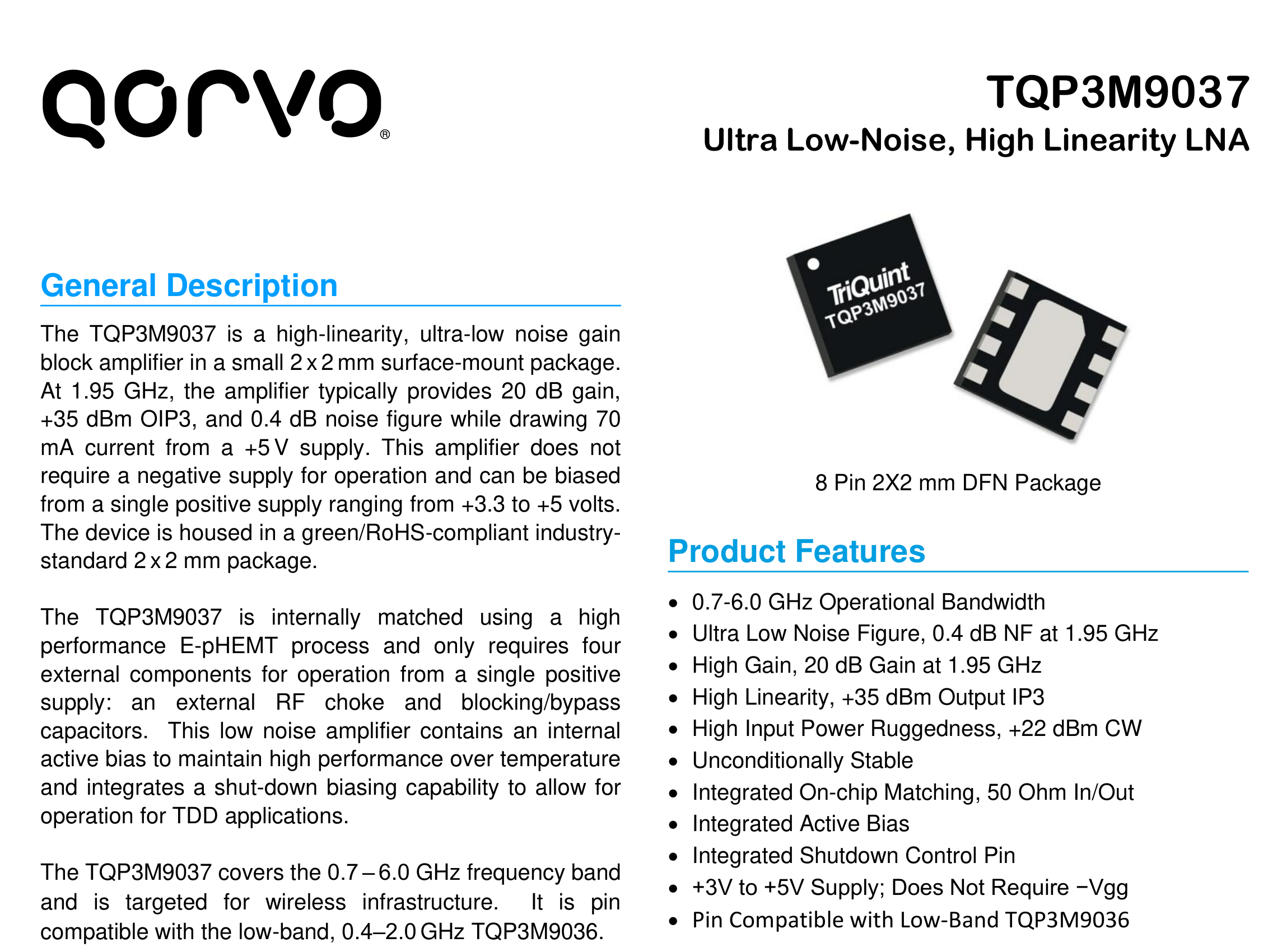
Last month, I wrote an article about the TQP3M9037 module — an Ultra Low-Noise, High-Linearity LNA. Despite being designed as a low-noise amplifier, its excellent linearity makes it a good candidate for a driver stage ahead of the main PA. Still, it’s important to keep its output level under control, because digital modulation signals tend to push amplifiers into compression more easily, resulting in nonlinear output.
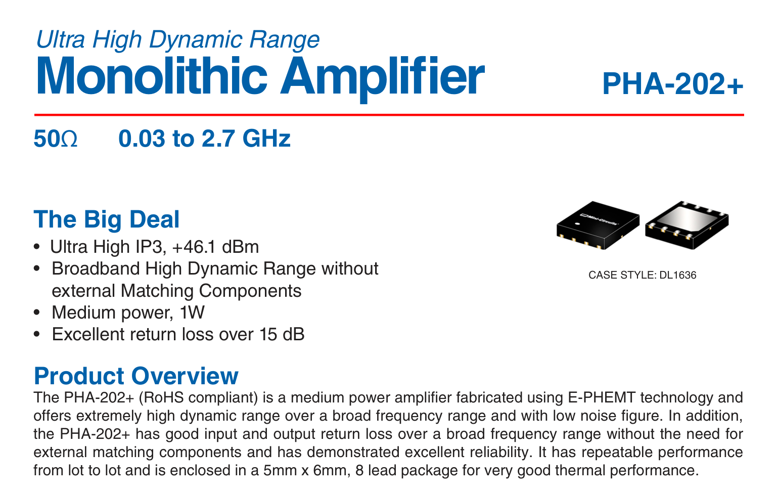
I also have a DIY PHA-202+ module on hand. This chip is a common PA driver amplifier with an output power of around 1 W, typically intended for Cellular, PCS, and LTE applications. Although it’s technically a driver, in this setup I decided to use it as the final stage amplifier, targeting roughly 1 W of RF output power.
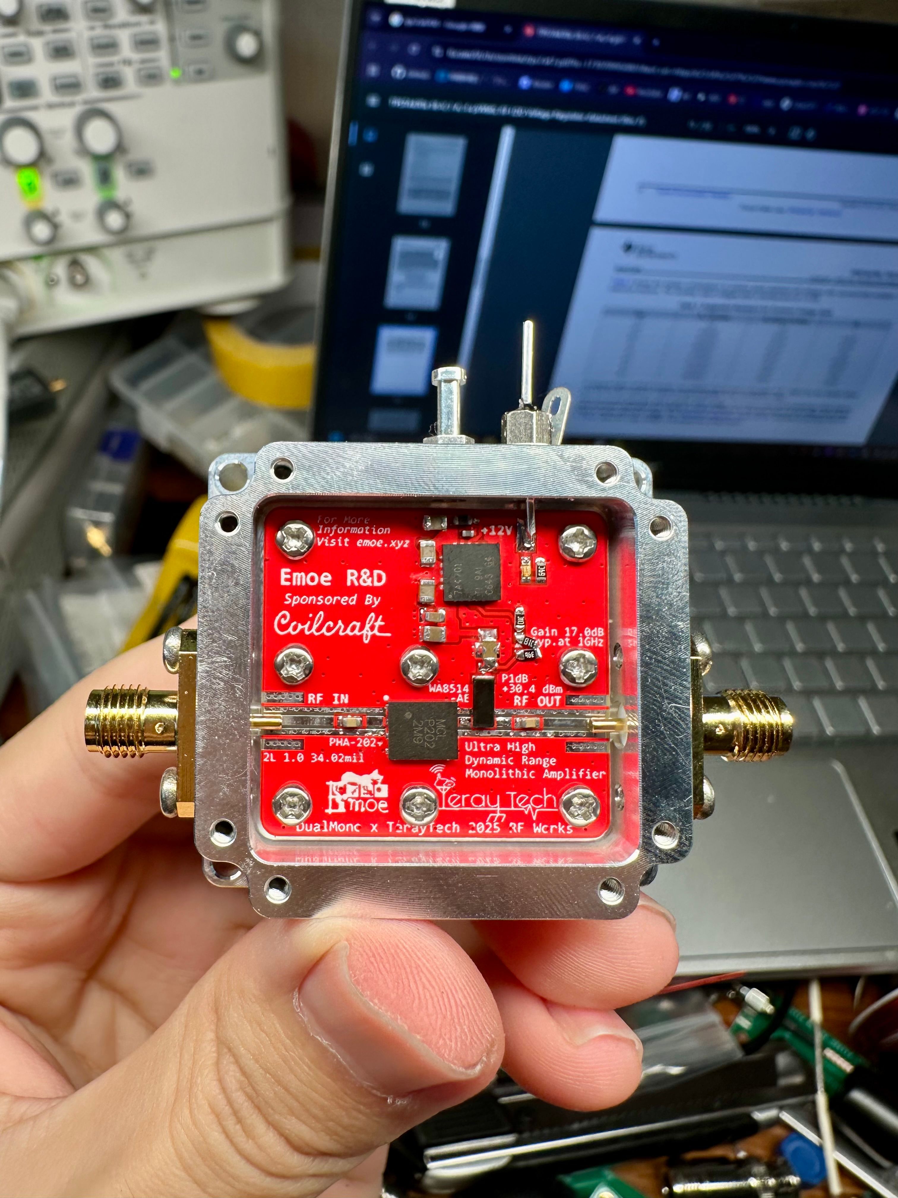
I plan to fine-tune the vector signal generator’s output amplitude to manage the overall EVM.
TQP has about 22dB gain, PHA has 17dB gain.
Later I found that it was indeed possible to control the EVM — it could be kept within 3%. But then I realized I hadn’t recorded any screenshots or photos, and honestly, I don’t really want to redo the measurement, since there isn’t much point. Nothing particularly new would come out of it anyway.
So far, all the results above were based on the vector signal generator — a single-carrier QAM signal. That made me wonder: could I feed the same amplifier chain with a real DVB-T modulator instead?
To find out, I pulled out the Zycast modulator I had tested a few weeks ago. After several rounds of connection and adjustment, I started to notice quite a few issues.
First, when I used the same configuration as before — the one tuned for 16-QAM output at around 1 W — the TV receiver showed 100% signal strength but 0% quality. In other words, the signal was there, but it was so badly distorted that the receiver couldn’t lock onto it at all.
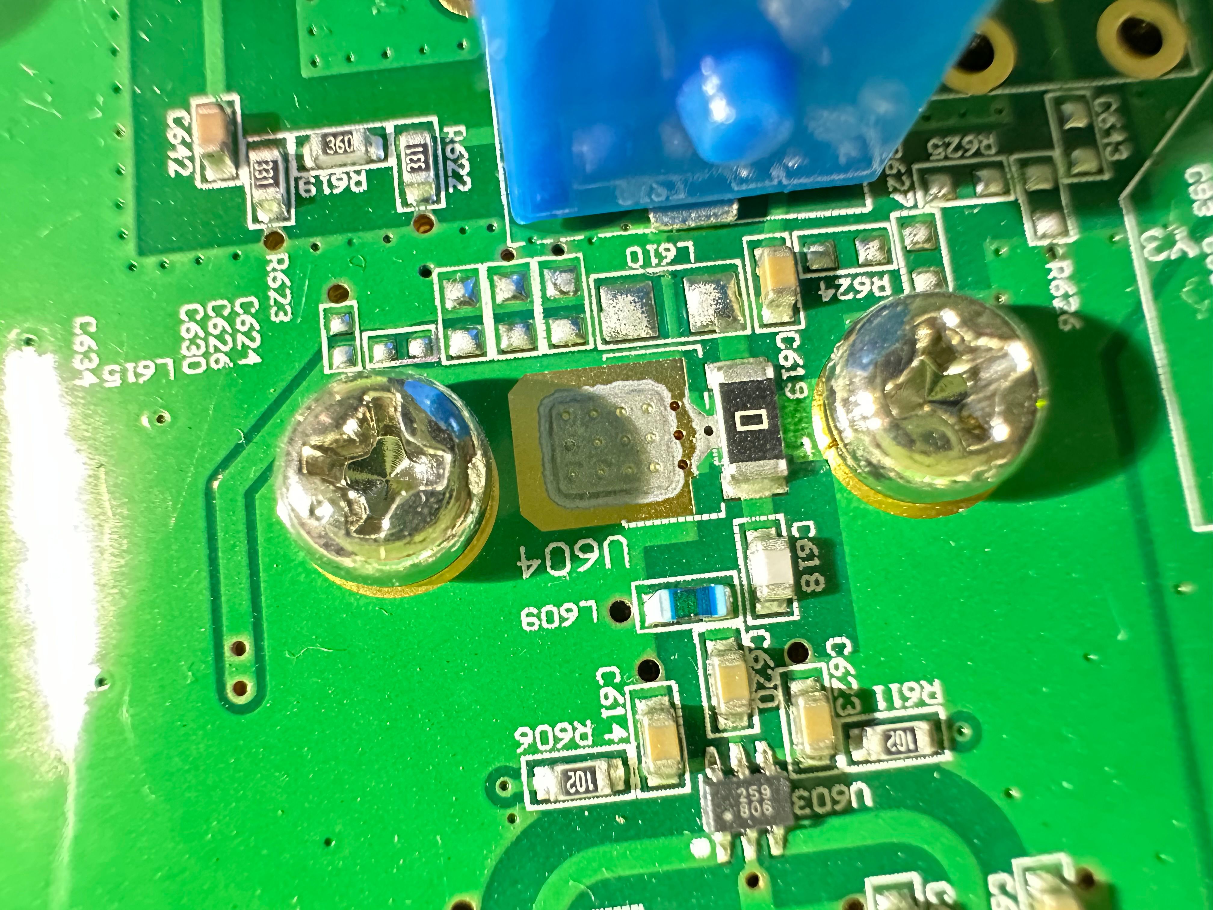
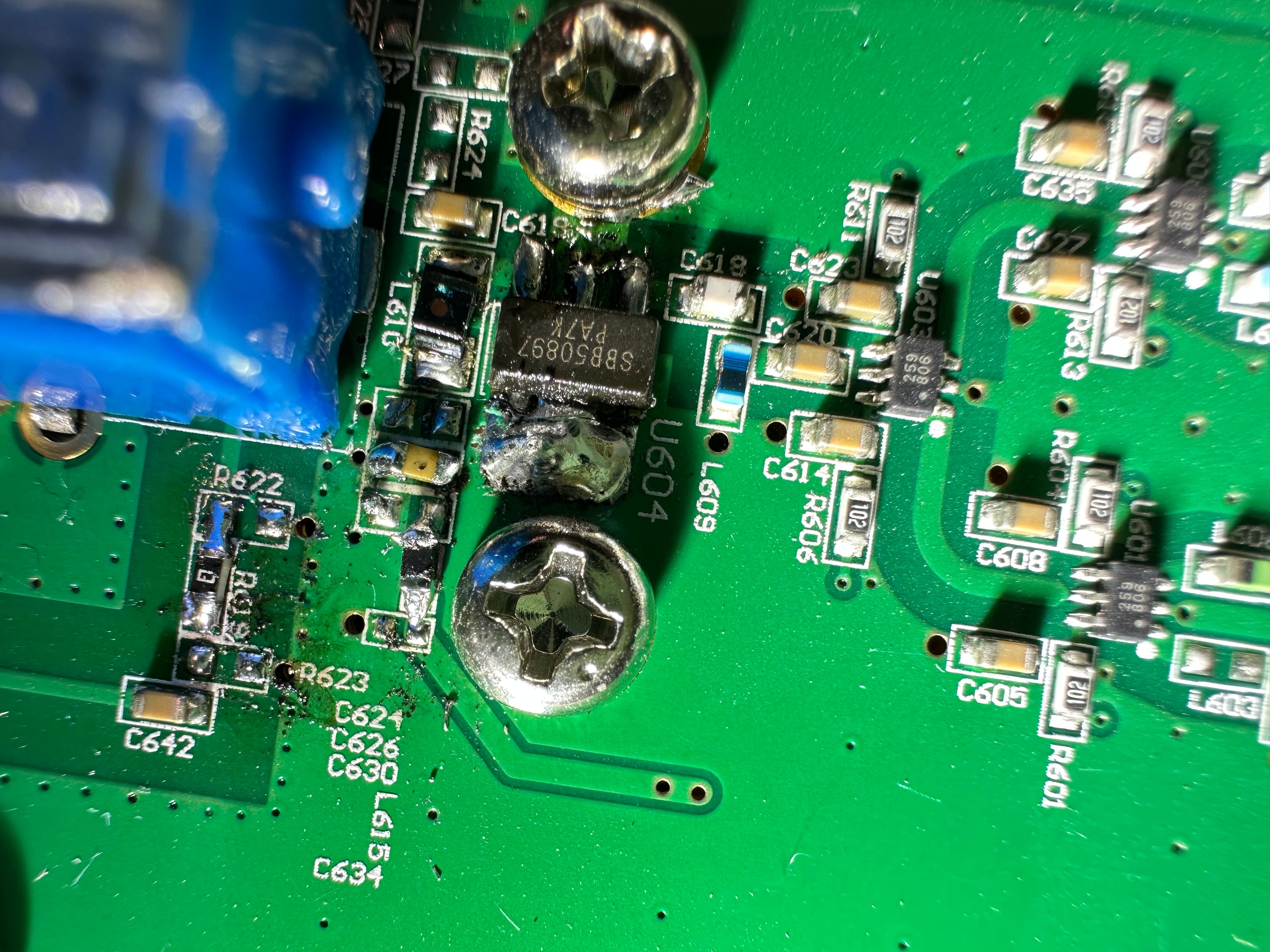
Since the modulator originally had no amplifier, I had soldered one in later. My first suspicion naturally went to that part, because it was an SBB-5089Z that I had removed from an FM modulator and installed inside.
(This is the original, there is an empty PAD for amplifier and biasing circuit as well)
(I added SBB-5089Z.)
I connected it directly to the TV receiver, and as expected, the signal strength reached about 90%, but the quality was still 0. So I decided to open the case and remove it.
Unexpectedly, this was indeed a case of good intentions causing trouble. An amplifier was supposed to be there, but it needed to be a high-linearity one. Obviously, the SBB-5089Z was not a good choice.
Yes, after removing it, the signal returned to normal. By the way, I forgot to mention that this modulator can only output 64-QAM signals, so the distortion would naturally be even worse.
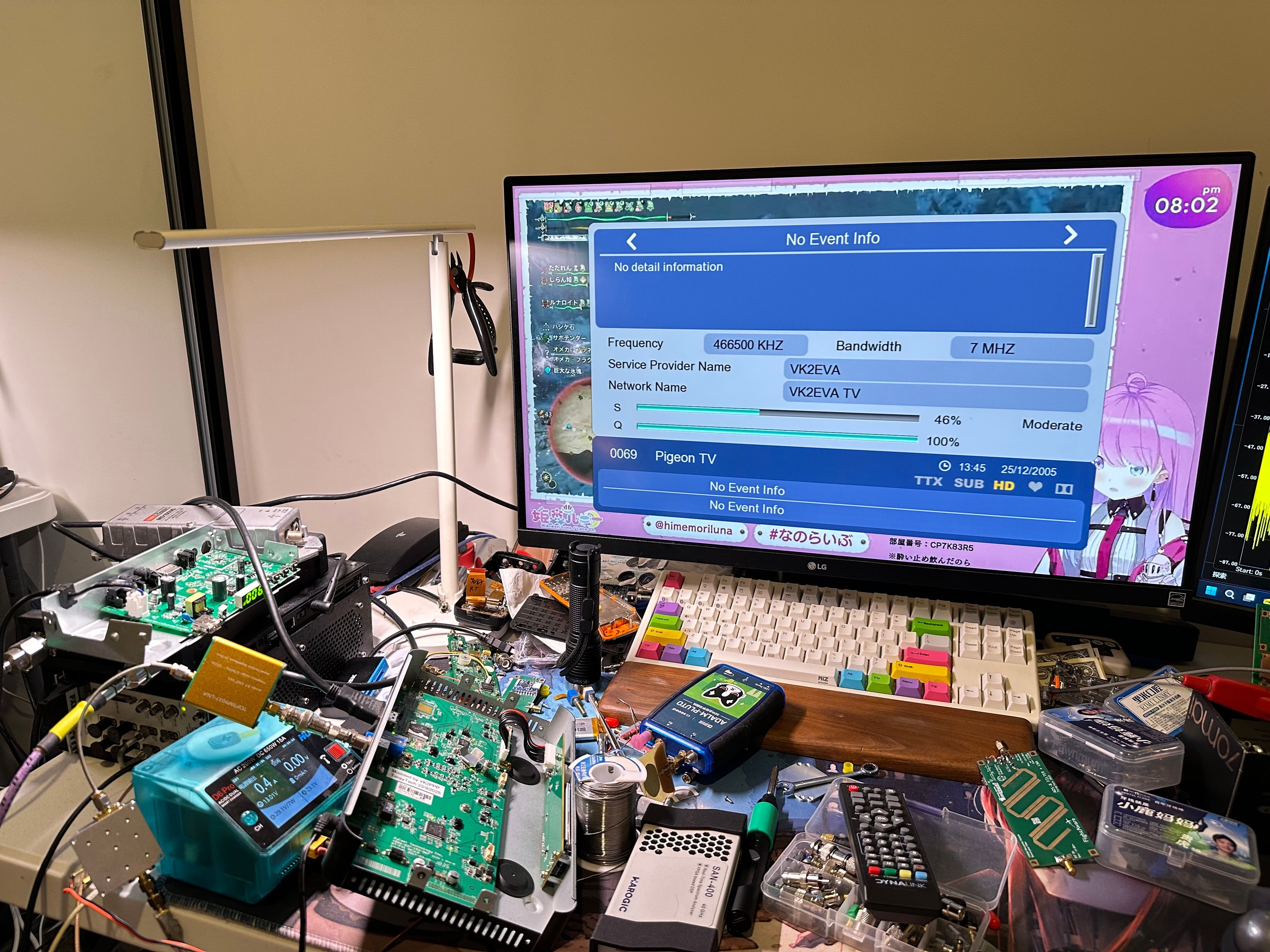
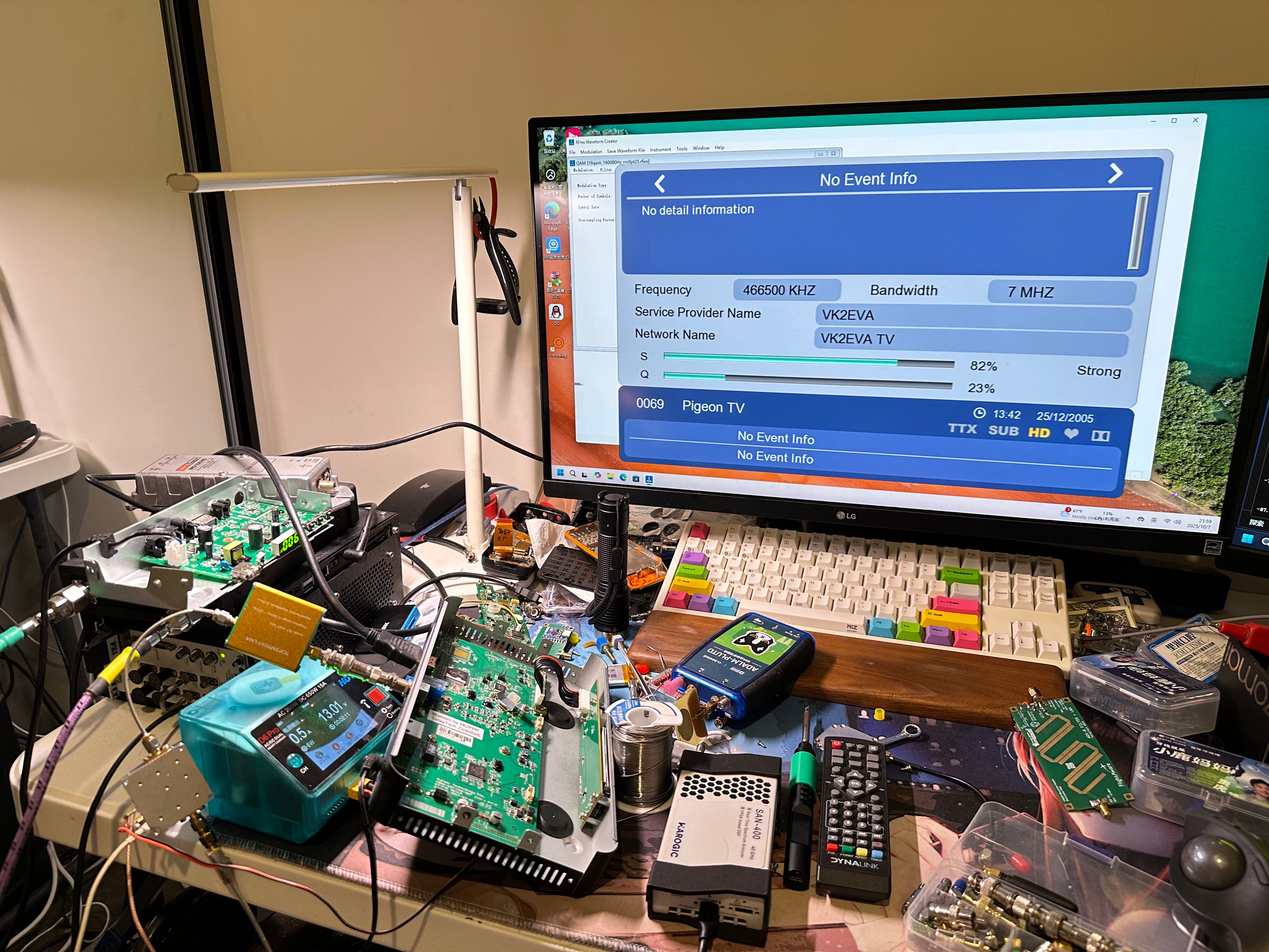
By adjusting the attenuation knob on the modulator, it is possible to control the output power of the PA. You can observe that at higher strength, the quality actually becomes lower. By reducing the input signal to the PA, the distortion decreases, allowing it to operate within its linear region, which naturally reduces distortion and improves overall signal quality.
Final Thoughts
Before ending, I want to say a few words as a conclusion.
I think I really underestimated the complexity of power amplifiers.
In the past, I wasn’t very clear about what kind of PA I actually needed for different applications. I thought most of them were more or less the same, differing only in price or efficiency or frequency ranges.
But now I’ve realized that a high-linear PA is exactly what I need for digital modulations. I’m not sure if I will continue experimenting with building power amplifiers — maybe I will, if I come up with new applications or experiments. For these particular tests, however, I’ll stop here. There isn’t much point in continuing, because the entire PA architecture would need to be redesigned from the ground up. I’ll need to perform a complete link budget and simulation before it can finally work the way it should.