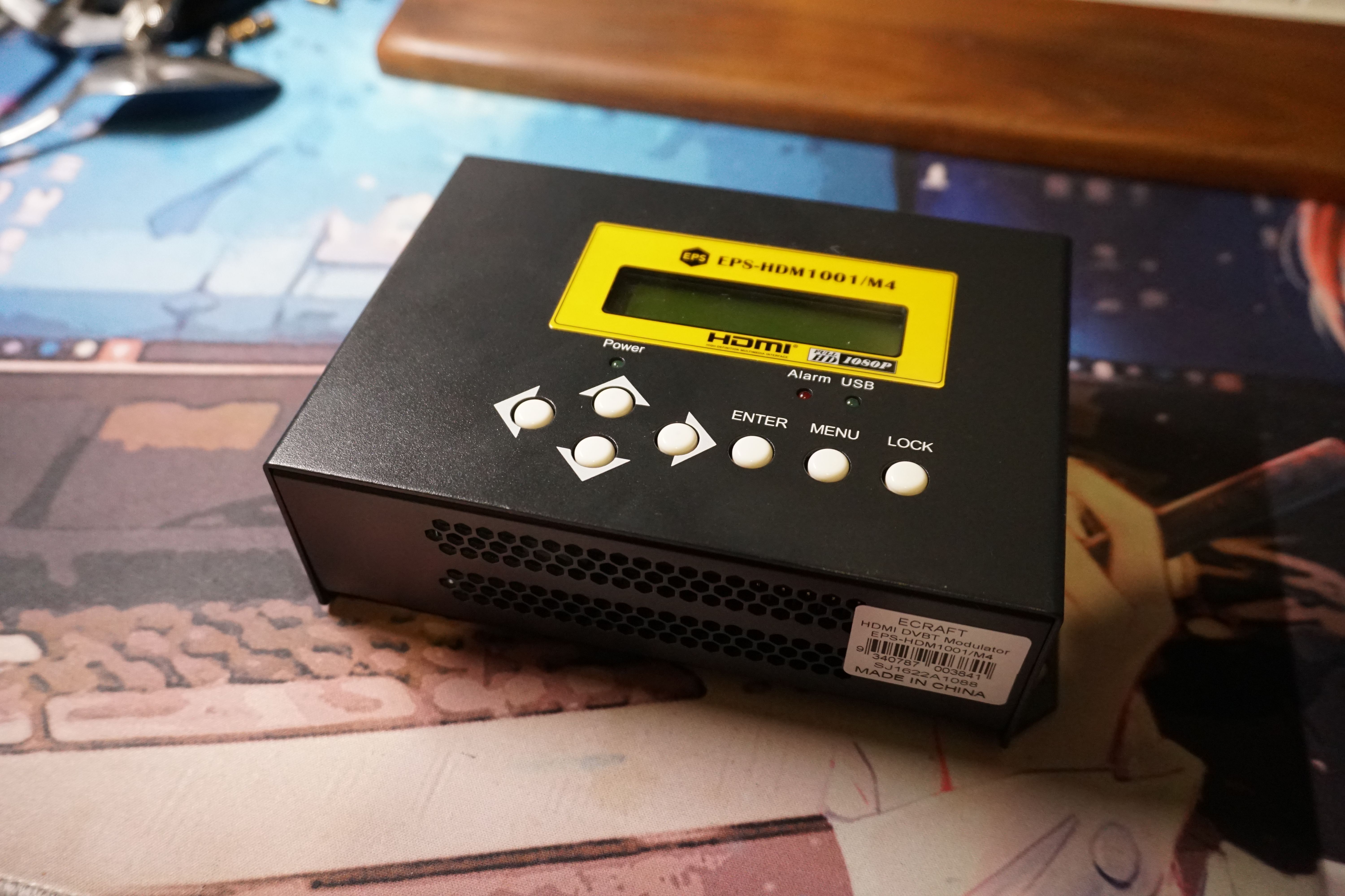
Ever since seeing Lewis’s modulator, I wanted one of my own. With two modulators, we could finally experiment with HAM TV. So I quickly took action and picked up an **ECRAFT **modulator, model EPS-HDM1001/M4, on Facebook for AU$150.
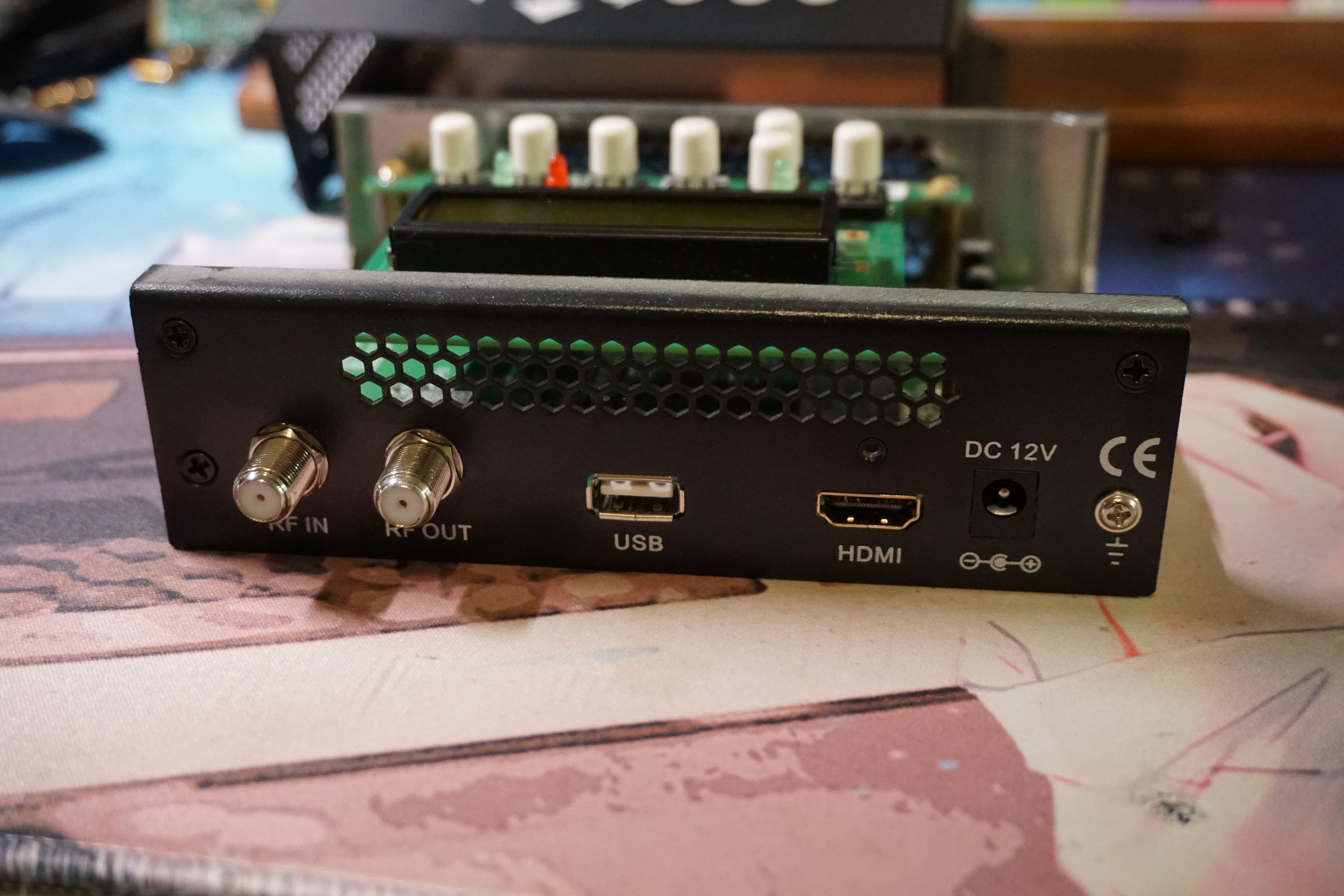
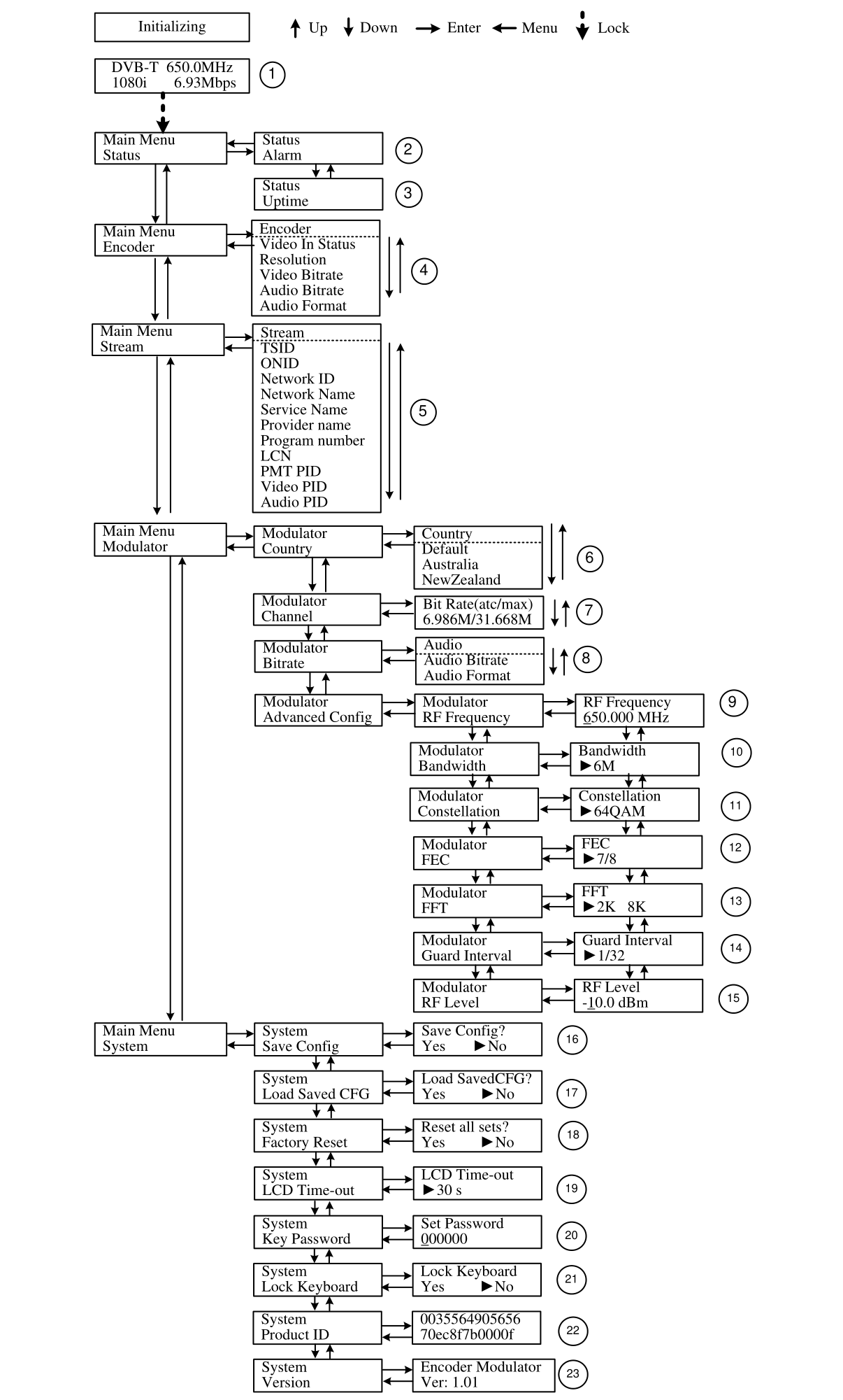
On the back panel, there are several interfaces: an RF input (only for signals from a satellite receiver, combined into a single path) and an RF output. The USB port is used solely for firmware updates and has no other functions. In addition, there’s an HDMI input, a power connector, and a grounding screw. The manual also includes a menu map, which is nice.
This unit is made in China mainland, which explains why it’s much cheaper and feels somewhat low-end. First, it’s very light—the casing is made of thin sheet metal. Second, it lacks Ethernet control and relies solely on simple buttons to adjust all parameters. On the bright side, its software is actually more feature-rich than the Taiwanese unit, supporting a wider range of settings.
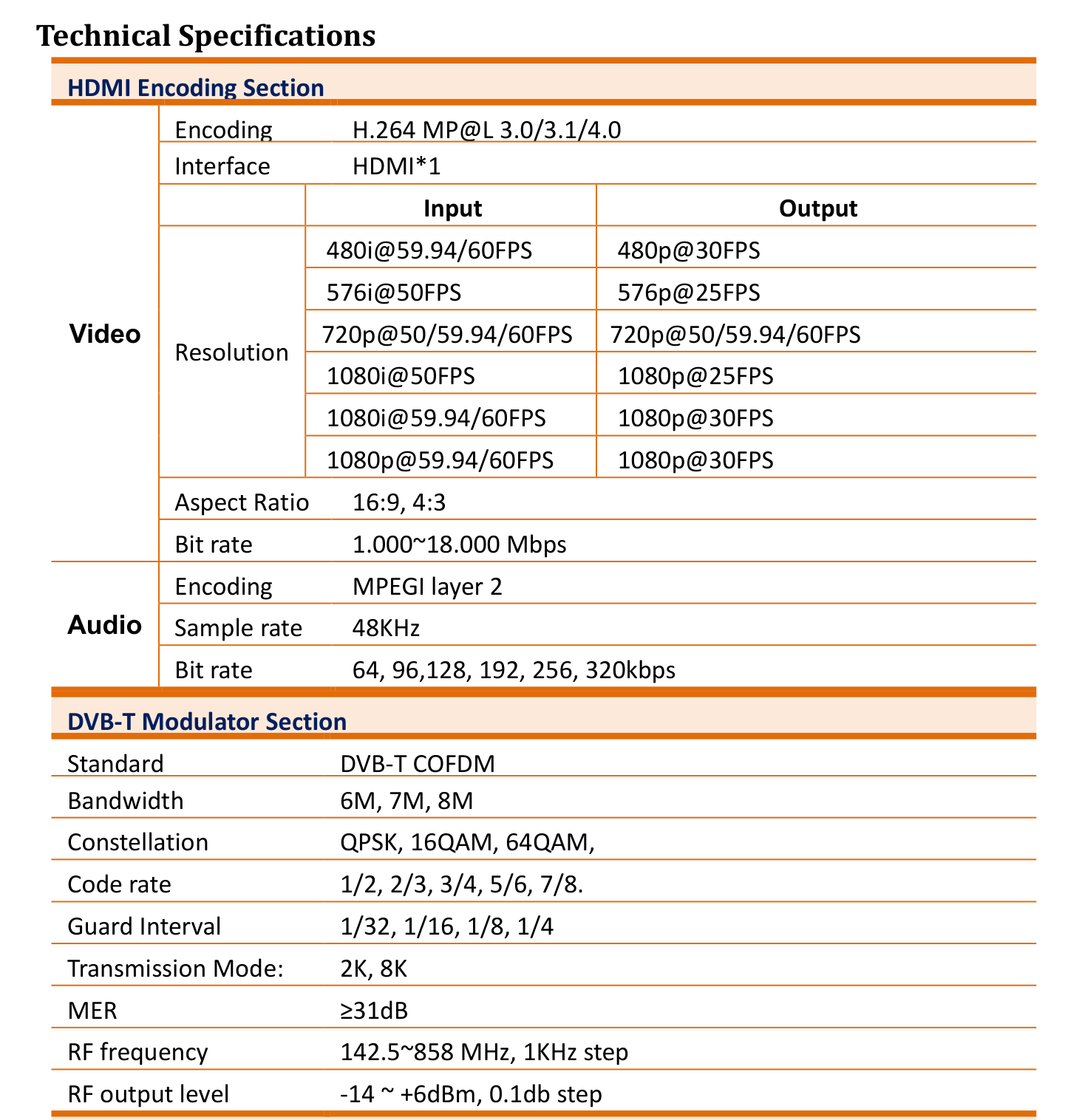
Being able to adjust more parameters is definitely a plus. In later experiments, I used this modulator to generate 16-QAM signals and successfully demodulated them in GNU Radio. I wasn’t able to demodulate 64-QAM due to some unresolved issues. On the bright side, both the code rate and guard interval are adjustable, which is pretty nice. The device’s MER measures around 31 dB, noticeably lower than the Taiwanese unit’s 39 dB. Somewhat lower signal quality. But as long as the signal can be demodulated, that’s really all that matters.
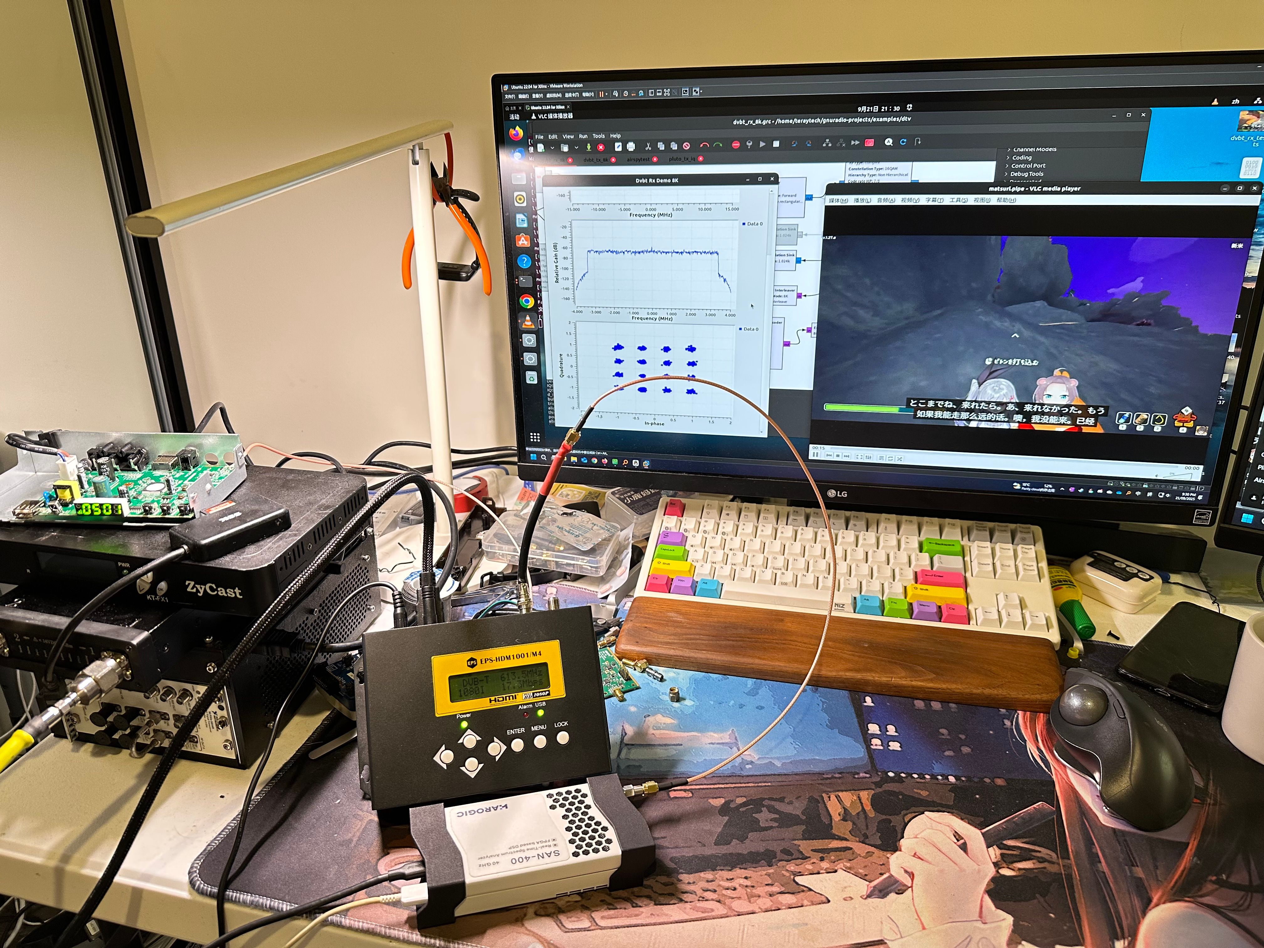
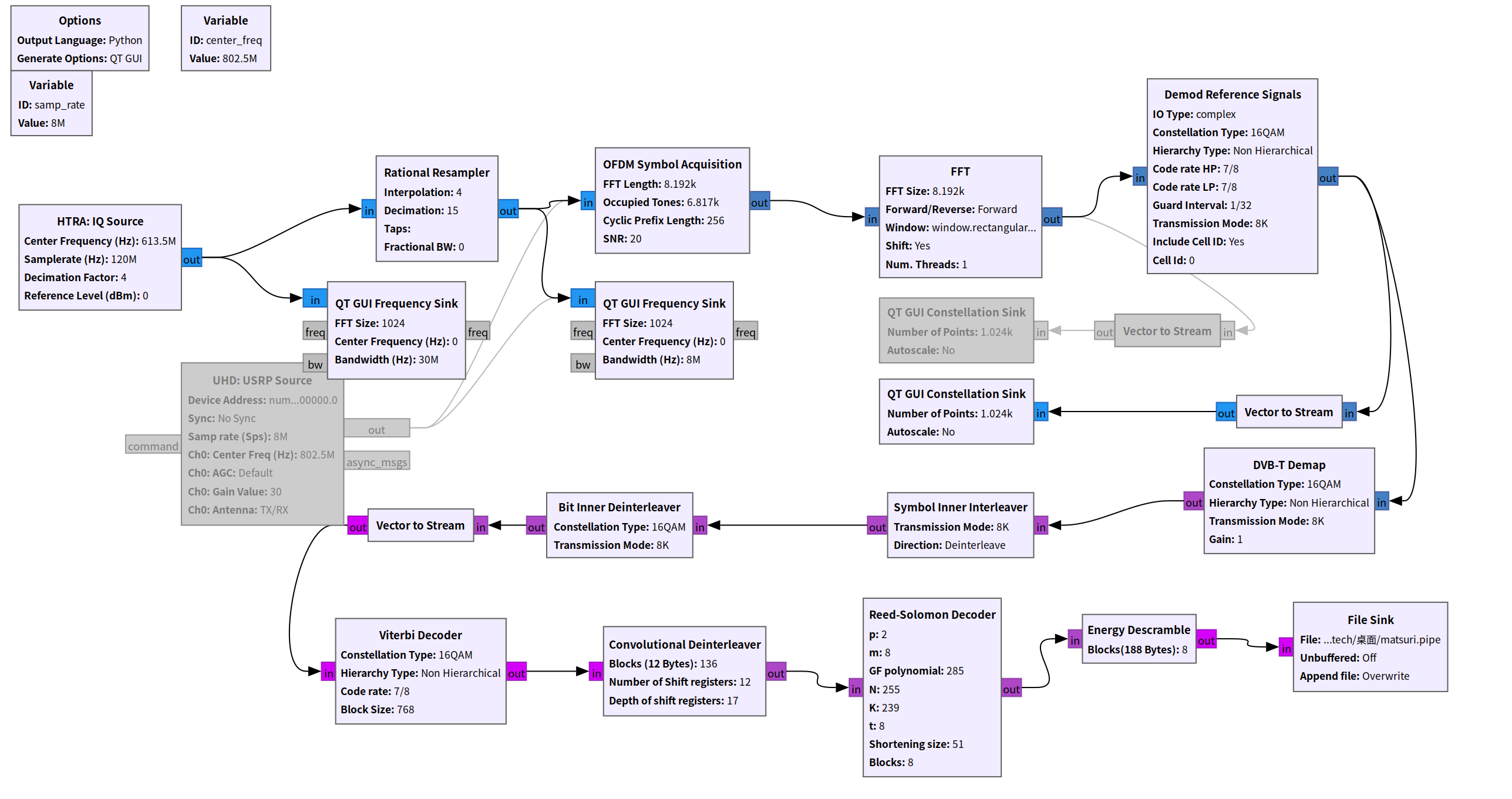
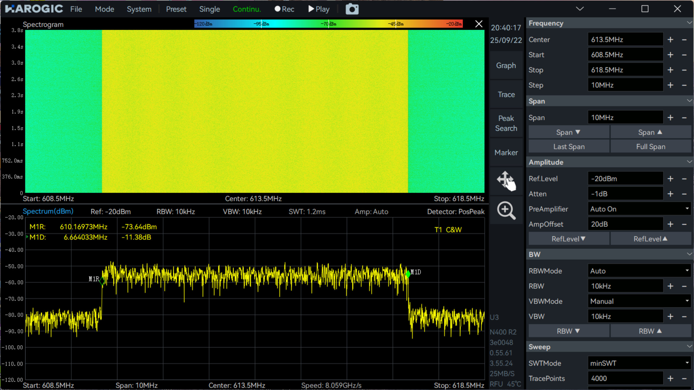
During testing, I connected the modulator to a real-time spectrum analyzer and streamed its IQ data directly into GNU Radio. By slightly modifying the parameters of the dvbt_rx_8k example from GNU Radio’s gr-dvbt library, I was able to successfully demodulate the signal. This was my first time demodulating a signal that fully complies with the DVB-T standard. All my previous experiments had relied on custom parameters because most of my SDR equipment had insufficient sampling rates and could only handle lower-spec versions of DVB-T.
Analysis
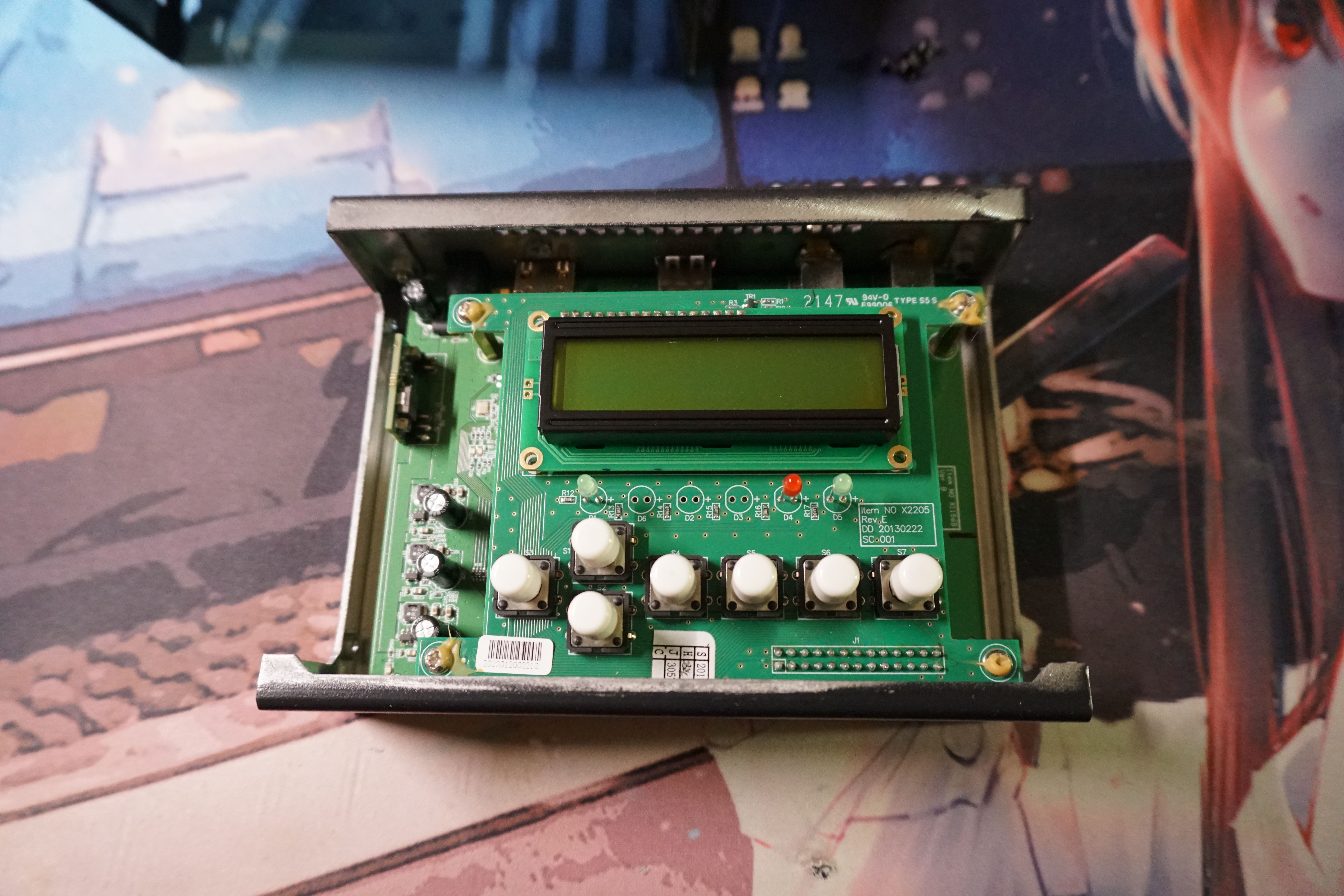
After opening the unit, the top section reveals a screen and button panel, connected to the lower PCB via pin headers and standoffs.
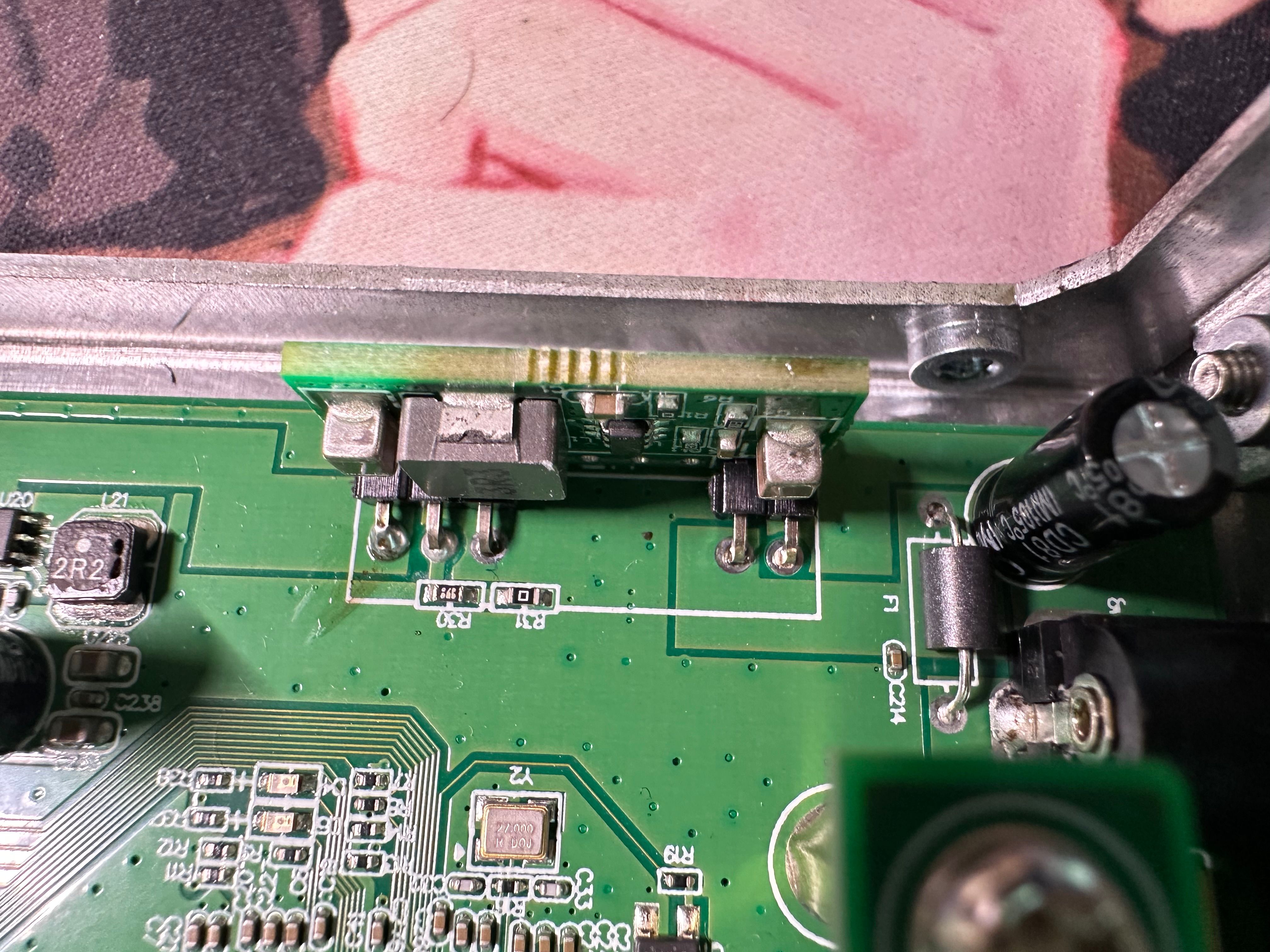
After removing the upper PCB, the mainboard underneath comes into view — and it immediately gives off a strong sense of cheapness. From left to right, you can see the RF input/output, the vector modulator, the baseband DAC, an ASIC integrating the HDMI encoder and controller, followed by the power circuitry on the right side, along with a through-hole power module.
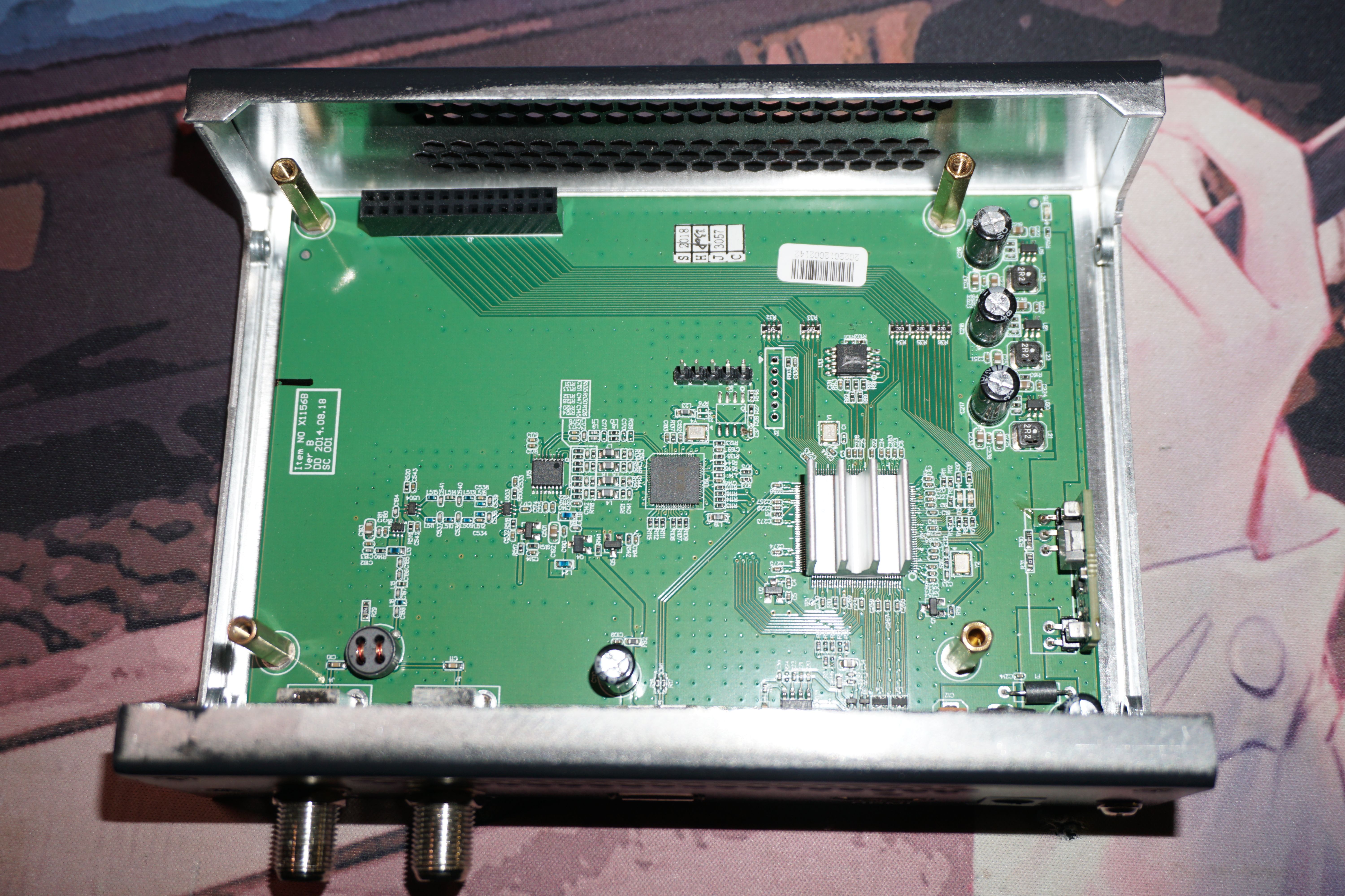
RF Input and Output
The RF input and output are coupled through a balun. One notable feature of this modulator’s design is its unusually high output power — up to +6 dBm adjustable — which explains the absence of any attenuation circuitry. However, it appears to include a basic high VSWR protection, likely implemented in a simple way to detect whether anything is connected to the RF output.
The chip labeled BC2 is an amplifier, very likely a PA or a gain block. Between U503 and U504, there is a filter switching network that allows band selection between UHF and VHF ranges. Moving further to the left, the vector modulator is an Analog Devices AD8345, a well-known wideband quadrature modulator.
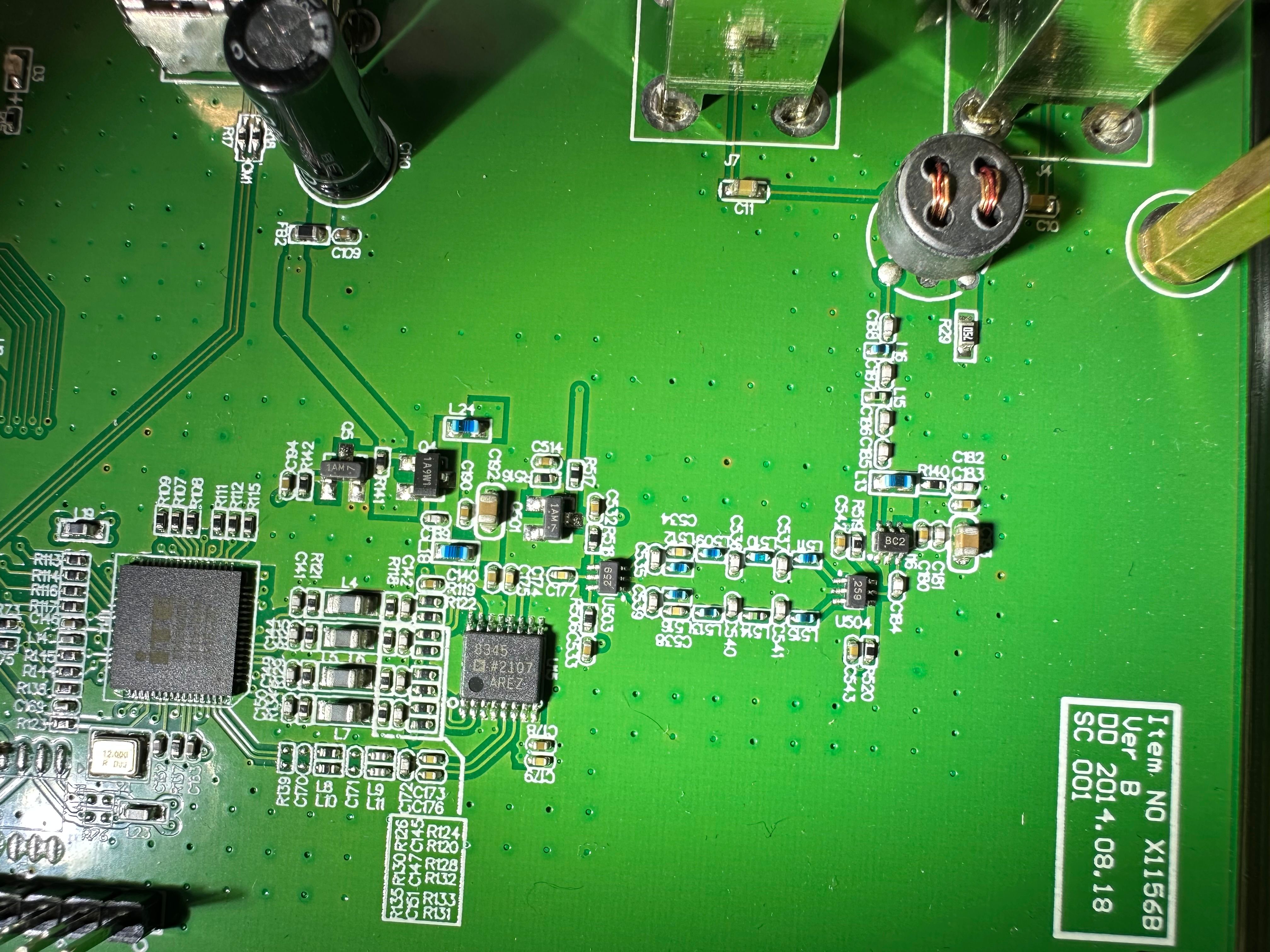
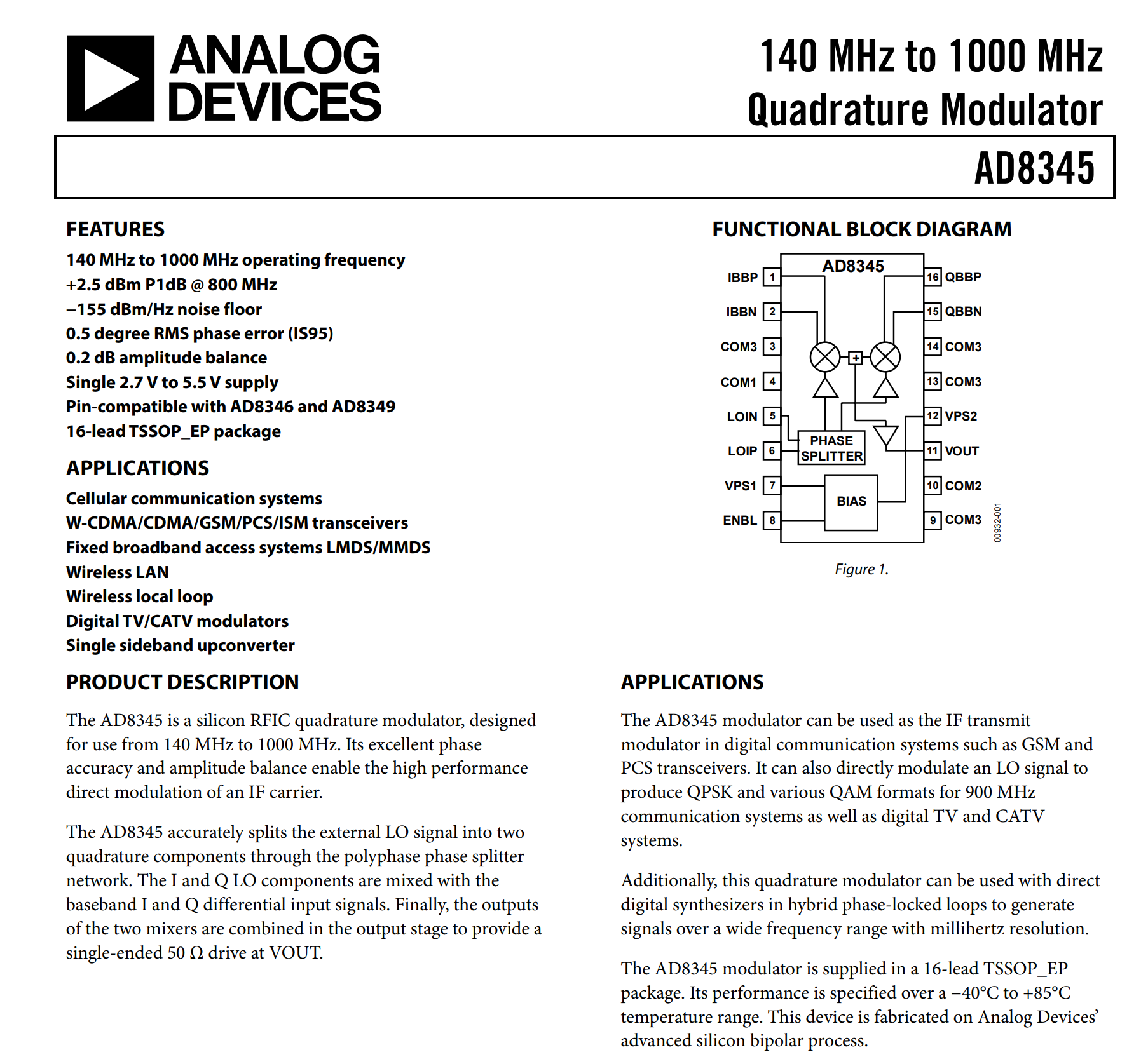
Mainland Chinese designs usually put a strong emphasis on cost efficiency, but they also tend to squeeze every bit of performance out of a chip. For DVB-T applications, the operating frequency tops out at around 800 MHz, so using a 1 GHz-class vector modulator here makes perfect sense.
Of course, a vector modulator like this requires a LO. The clever part is that the encoder chip itself provides the LO output for the modulator, eliminating the need for an extra PLL stage. The key device here is the ITE IT9507 transmitter — essentially a black-box ASIC. Its documentation is locked behind NDA, and only a handful of high-level descriptions are publicly available.
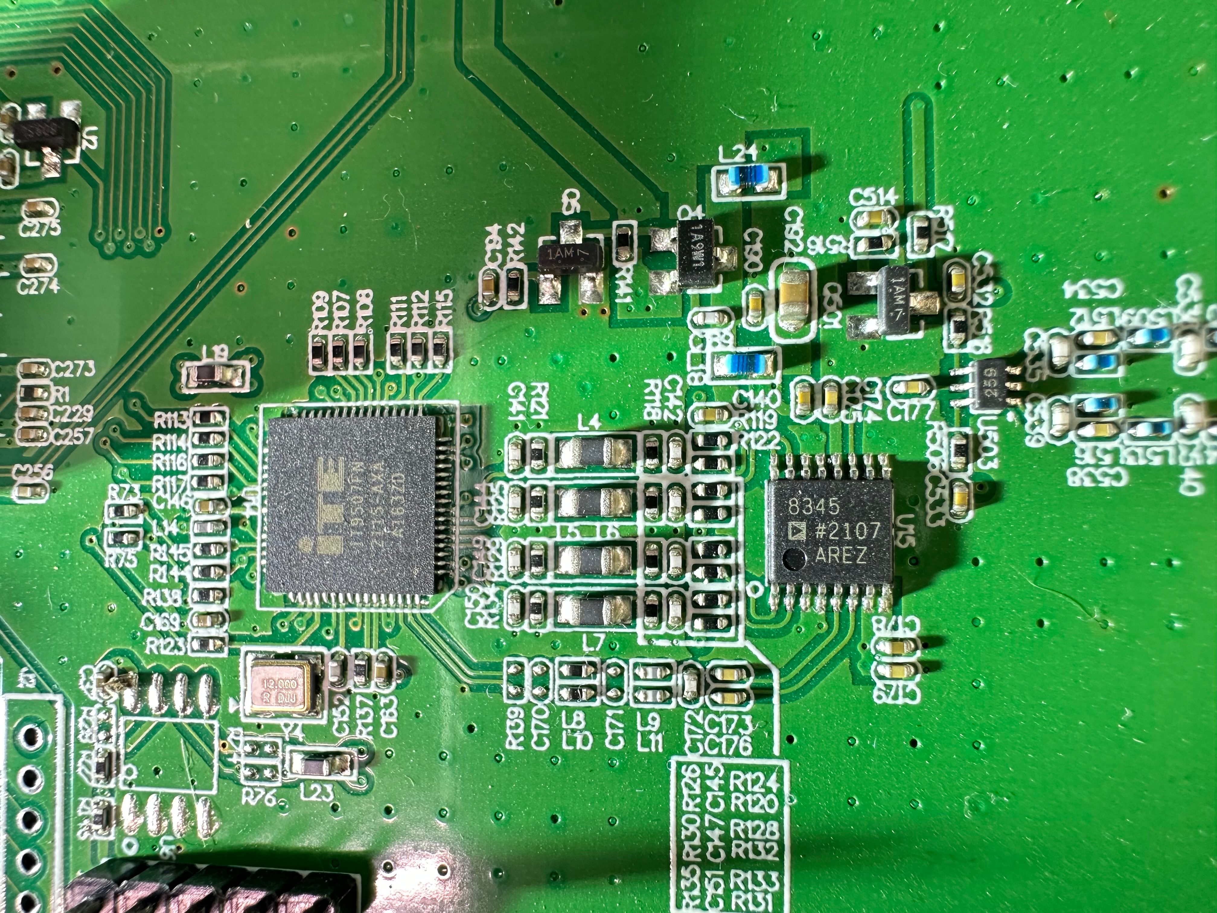
You can also spot 2 differential Nyquist anti-aliasing filters built from discrete capacitors and inductors. At the very bottom of the layout runs the LO signal path, feeding the vector modulator.
The main encoder is a big QFP package with roughly 100 pins. Unfortunately, its markings are hidden under a strongly glued head sink, and I don’t want to risk damaging the chip just to identify it. From its placement and role in the system, it’s most likely responsible for handling the user interface controls as well as performing some basic HDMI encoding tasks.
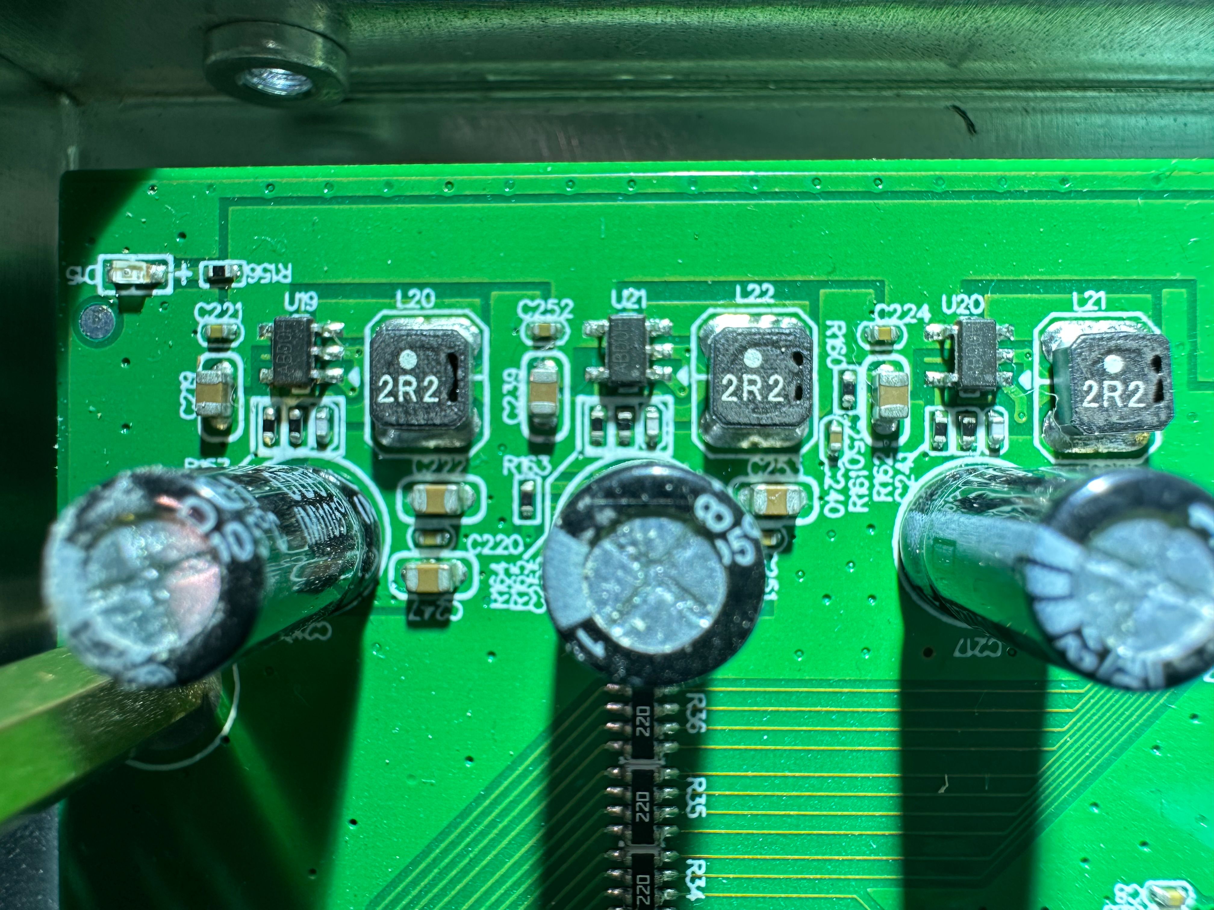
The remaining section of the board is dedicated to the power supply circuitry. It’s a three-rail design, most likely used to provide three different voltage domains required by the encoder, modulator, and RF front end.
There’s also a rather odd-looking power module on the board. It’s interesting because they could have easily integrated this part directly onto the PCB. My guess is that it might be leftover stock from a previous project, or perhaps chosen for better thermal handling. In practice, it seems to function more like an input transformer, stepping the supply down to 5 V.
Measurements
BW 6.7M
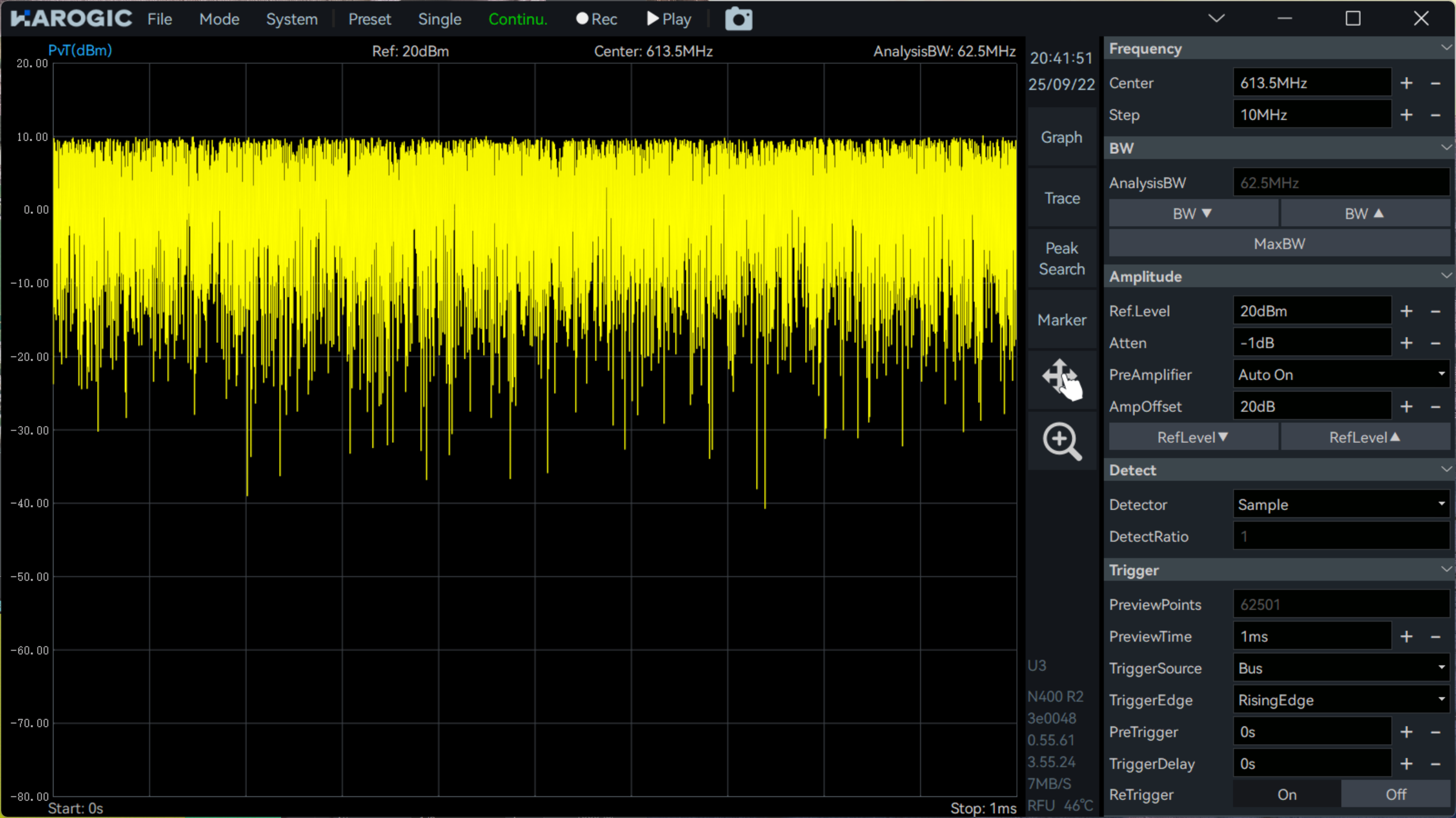
In the power vs time mode, we can see peak signal strength is close to +10dBm, which is pretty large. I put a 20dB attenuator before the spectrum input.
Conclusion
The ECRAFT EPS-HDM1001/M4 modulator may feel a bit cheap at first glance, but it’s surprisingly capable. Its flexible parameter settings, adjustable code rate and guard interval, and built-in baseband and RF processing make it perfect for HAM TV experiments. While its MER is lower than higher-end units, it’s more than sufficient for practical demodulation, and features like the integrated LO from the encoder chip make experimentation straightforward. Overall, it’s a fun, hands-on way to learn about DVB-T signal generation and digital video transmission.