I’ve got this super cheap LNA module that uses the TQP3M9037 chip. It cost only me CN¥40 (~$6) including shipping. Pretty sure I bought it a few years back, and every once in a while when I need it, I just dig it out and throw it into the setup. Sometimes adding just a few dB of gain makes the signal way easier to deal with.
Thing is, even though I’ve had a VNA for ages, I never actually tested this it. So I figured I’d write a post and take a closer look at its performance, especially since I couldn’t find any S-parameter info about it anywhere online.
The Circuit
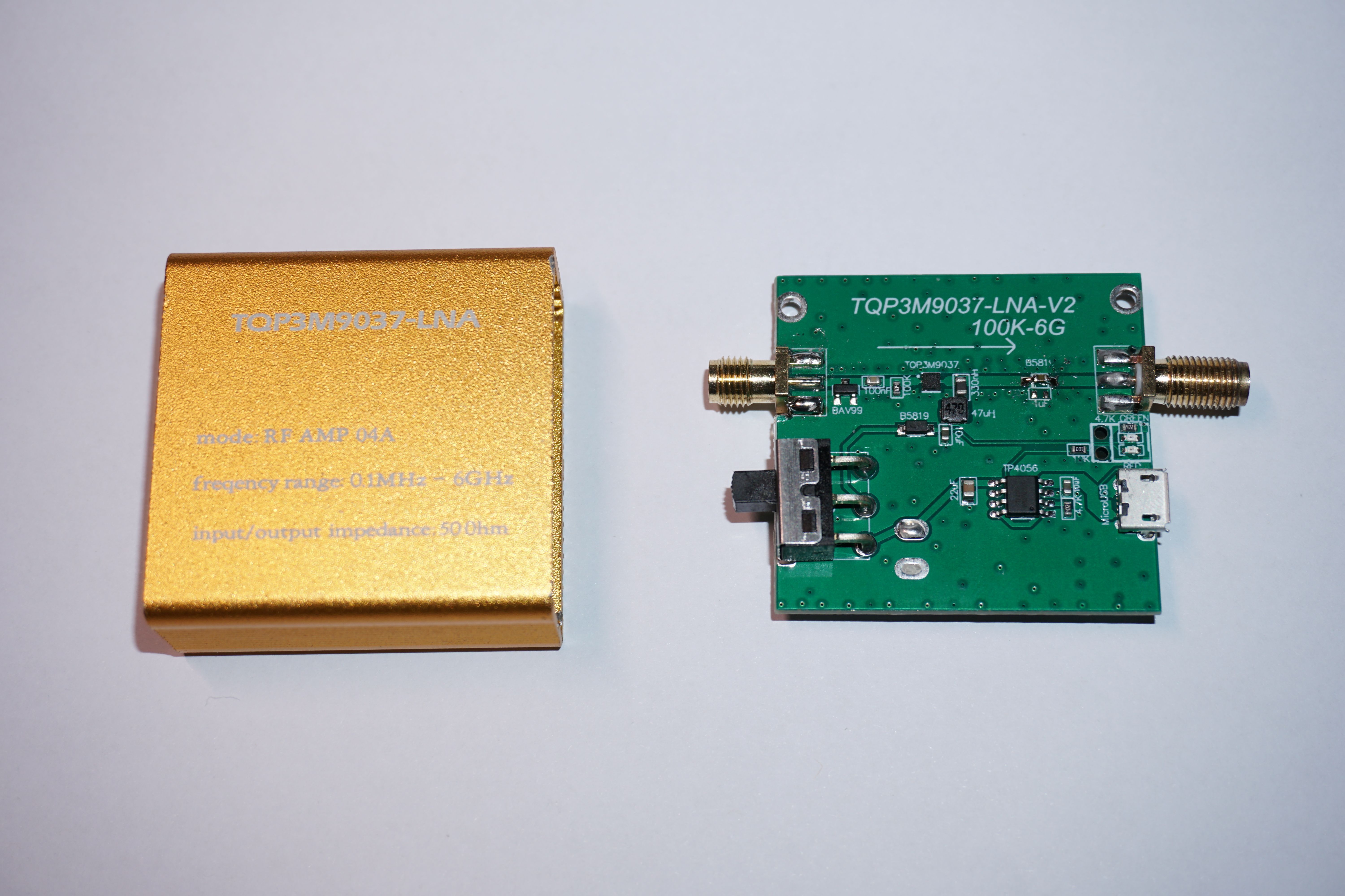
First off, let’s take a look at what’s actually on this board. Honestly, there aren’t many components at all—and that’s pretty much why it can be sold this cheap. The PCB quality is pretty bad too. You can tell it was made at a low-cost fab house to save money: the solder mask has clumps of green oil around the via.
The board is 1.6 mm thick, which usually means you’d need wider traces to hit 50 Ω characteristic impedance. Clearly, there’s no impedance control here. To make things worse, the copper clearance on the top and bottom sides isn’t even symmetrical.
My guess this probably isn’t an original design. It looks more like some vendor just cloned an existing design—copied most of the circuit, but left out all the finer details.
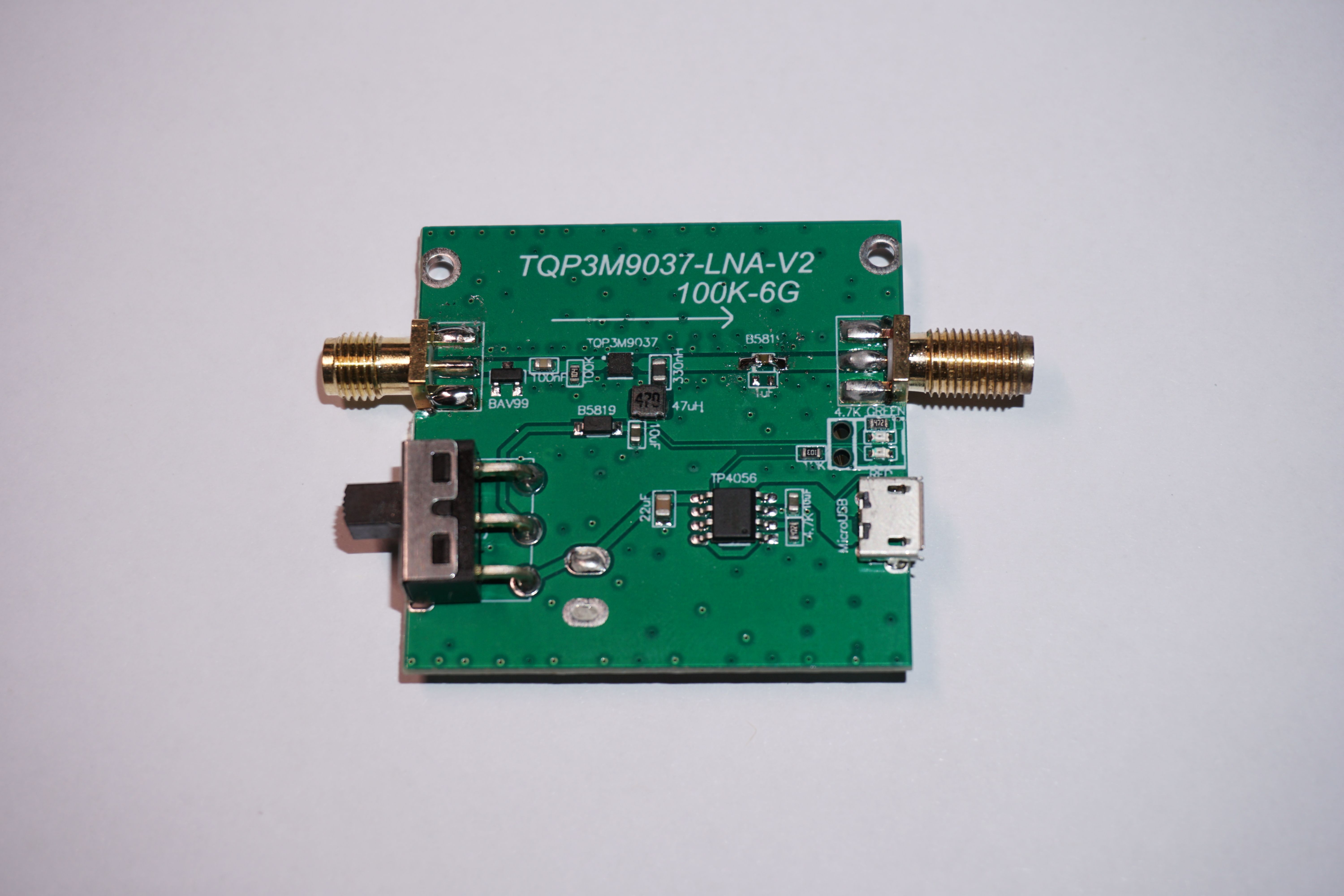
The signal path goes from left to right. First, there’s a BAV99 in parallel, which is usually for ESD protection—you’ll see the same thing on RTL-SDR front ends. Then comes a DC-blocking capacitor.
There’s also a 100K SMD resistor to ground. Its job is to give the LNA input a DC return path and an ESD discharge path, basically keeping the input potential stable without messing up the RF matching. After that, the signal goes into the TQP3M9037 chip.
On the output side, they used a 330 nH ferrite bead together with a 47 µH wire-wound inductor for the biasing. Then there’s a 1N5819 Schottky diode. The idea here seems to be that you can power the board using the bias-T feature of an SDR, so you don’t have to keep charging the battery separately. But I removed it, since I don’t really use it.
And the SMA connector on the output is soldered crooked. The one on the left was such poor quality that it actually broke off—since it wasn’t soldered on the back side, it just snapped when I screwed in the SMA cable. I ended up replacing it with a regular connector, though I didn’t have the full-threaded kind.
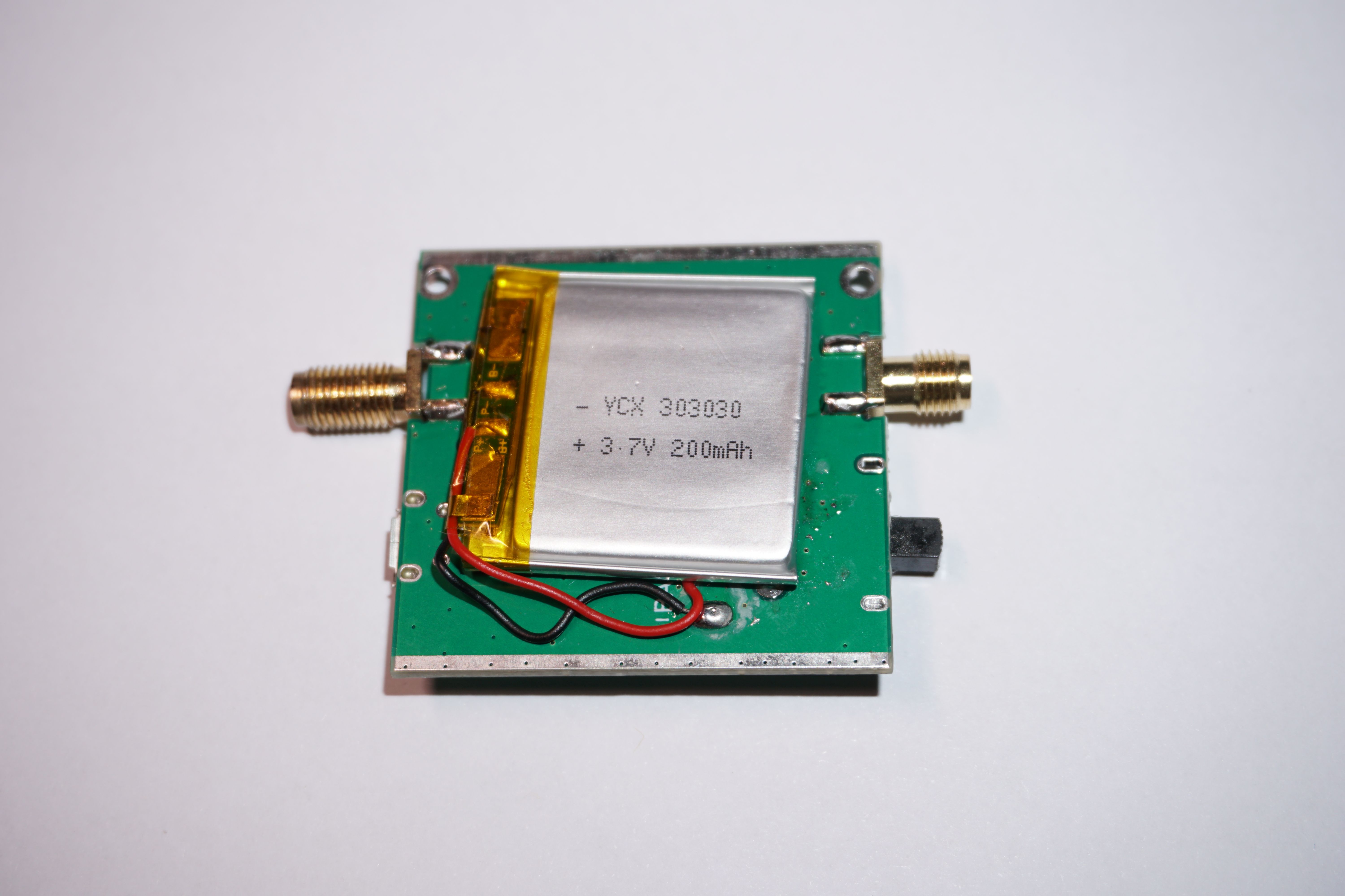
There’s also a TP4056 charging IC pretty standard stuff. The output from the switch goes through another 5819 diode, which is there to prevent reverse current flowing back into the battery if you’re using an external bias-T. On the back side, there’s a 3.7 V / 200 mAh Li-ion cell.
The S param
Really bad TBH. This thing is basically only usable below 3 GHz. Once you go past 4 GHz, it doesn’t give you gain anymore, it adds loss.
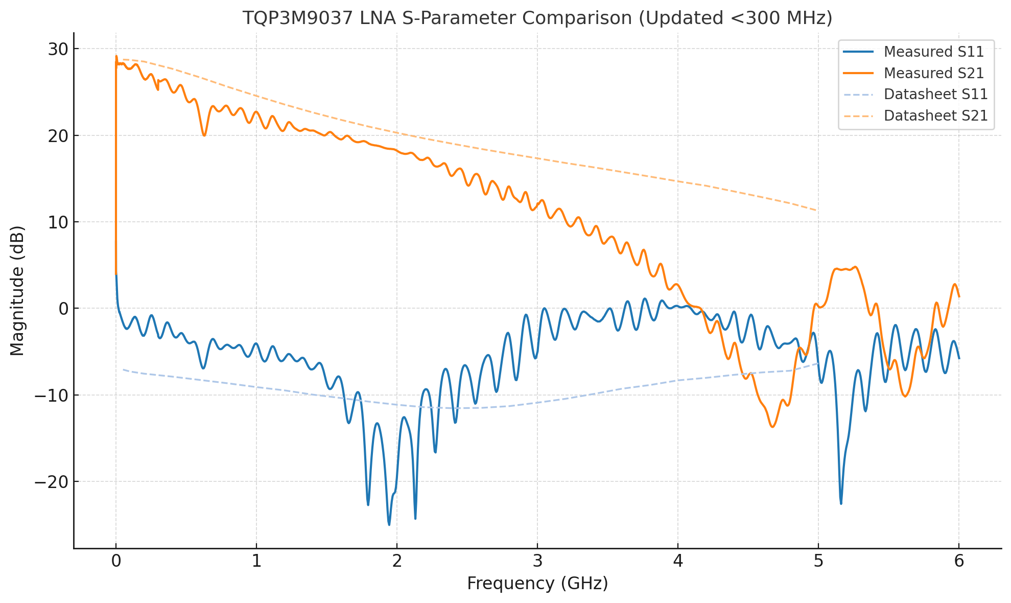
In theory, with a proper design, this chip can definitely work up to 6 GHz. The case even says its frequency range is from 100 kHz to 6 GHz. But let’s be real—that’s total nonsense. At this price point, expecting any kind of flat response is just wishful thinking.
Simple way to improve
Further analysis shows that the input BAV99 diodes have a significant impact on the overall gain. The primary reason is their parasitic junction capacitance and series resistance at RF frequencies, which introduce additional insertion loss. In addition, the non-linear characteristics of the diodes slightly disturb the input impedance match, resulting in degraded power transfer to the LNA. While they do provide ESD protection, this comes at the cost of reduced gain and less optimal RF performance.
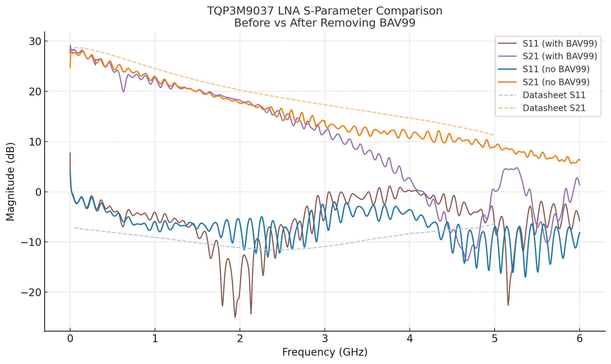
By simply removing the input diodes, the amplifier’s intrinsic performance can be effectively improved. As shown in the measurement results, the sharp roll-off above 3 GHz is noticeably reduced after their removal. The response now aligns more closely with the typical attenuation expected from the PCB and connectors, a smoother and more consistent decline. At 6 GHz the device still provides several dB of gain, making it more possible to operate for 6GHz applications.
Conclusion
Overall, this little Taobao/Aliexpress LNA is exactly what you’d expect for the price. Out of the box it works decently below ~3 GHz, but anything higher quickly falls apart with gain dropping into actual loss. The poor PCB layout, cheap components, and unnecessary protection parts all drag down what the TQP3M9037 chip is actually capable of.
That said, with a few simple tweaks—like removing the input diodes—you can recover quite a bit of performance and even push it into the 6 GHz range with usable gain. So while it’s definitely not a “serious” lab-grade amplifier, it’s still a fun and cheap module to play with, and a good reminder that sometimes the silicon is fine, but the board design is what really makes or breaks the RF performance.